1
\$\begingroup\$

So I'm dealing with an issue involving driving FCOB PWM control LED strips (BTF-LIGHTING) with my ESP32-S3. These are lights that are on my ceiling in my room, and are being used as general lighting. These strips are the non-addressable type, meaning I am controlling them by controlling the gate voltage of the MOSFET to turn on and off the LED's. The gate itself is controlled by an ESP32-S3.

Light Circuit Specs:

  • LED Light strips are about 50 ft in length
  • Power Supply I'm using is 24 V, 5 A
  • Max LED Current/Power consumed is about 1.875A/45W (on the White Channel)
  • Length of Power Supply 24V wires is about 10 ft
  • Wire Gauge of Power Supply wires is 18 AWG

So my main issue is that when I just want to turn an LED color channel on at 100% brightness (i.e. turning MOSFET ON 100% of the time), then my lights are running as expected. But if I want to PWM my lights, then what happens is my circuit works as intended for a little bit, but then I start to see this “flash flickering effect” coming from my lights, which might be a sign the MCU is resetting itself. The lights will turn on for maybe 100 ms, turn off for 2 seconds, and the cycle will repeat. I'm only driving the white channel currently, so the current is just under 2 A. I'm not sure what the PWM frequency is since I don't have an oscilloscope, but I'm using the analogWrite function in Arduino. So I'm assuming for now it's 490 Hz. So the issue right now is that the MCU seems to reset itself continuously when I am PWMing my LED lights, and I'm trying to figure out how to fix it.

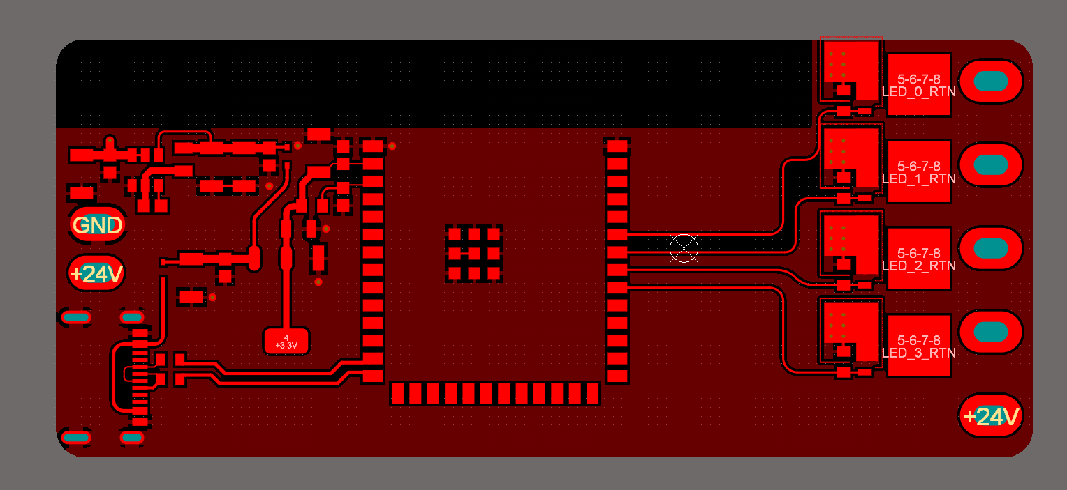
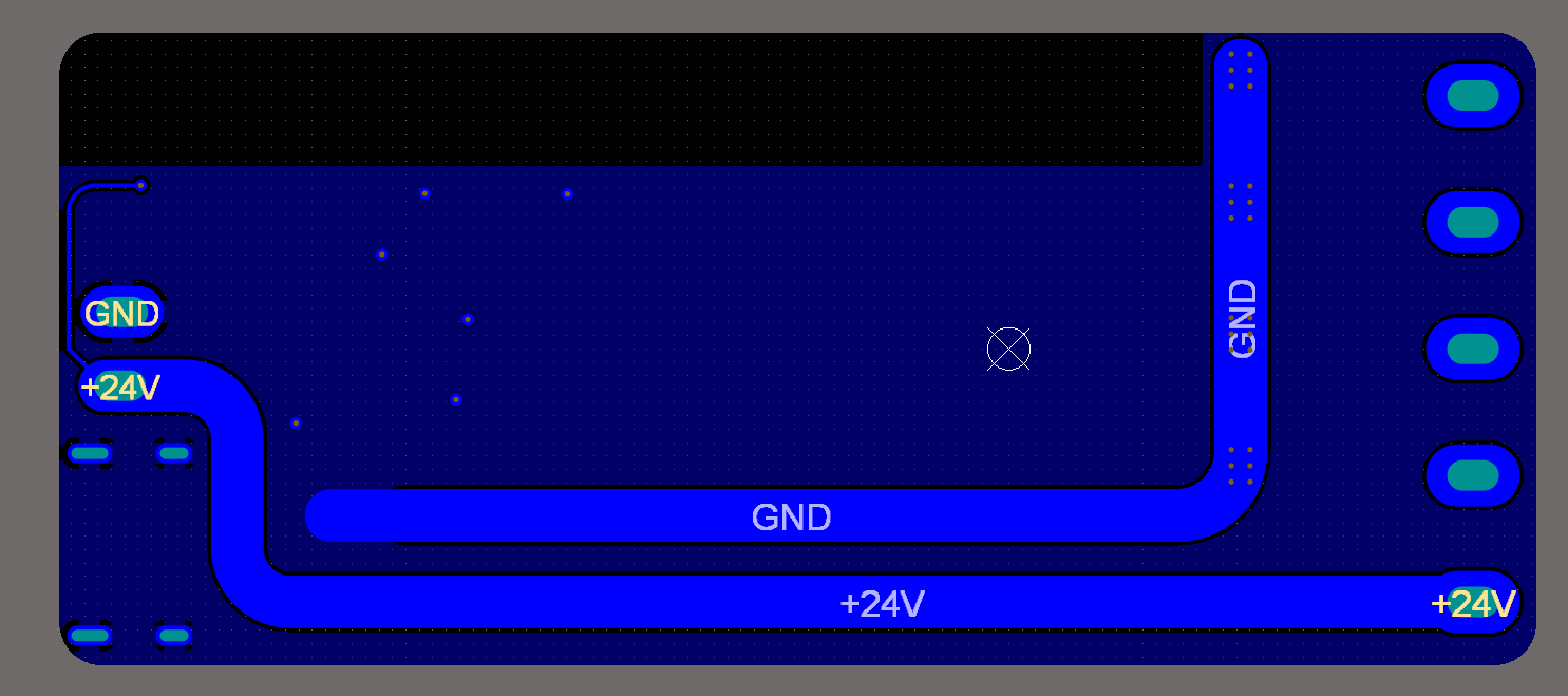
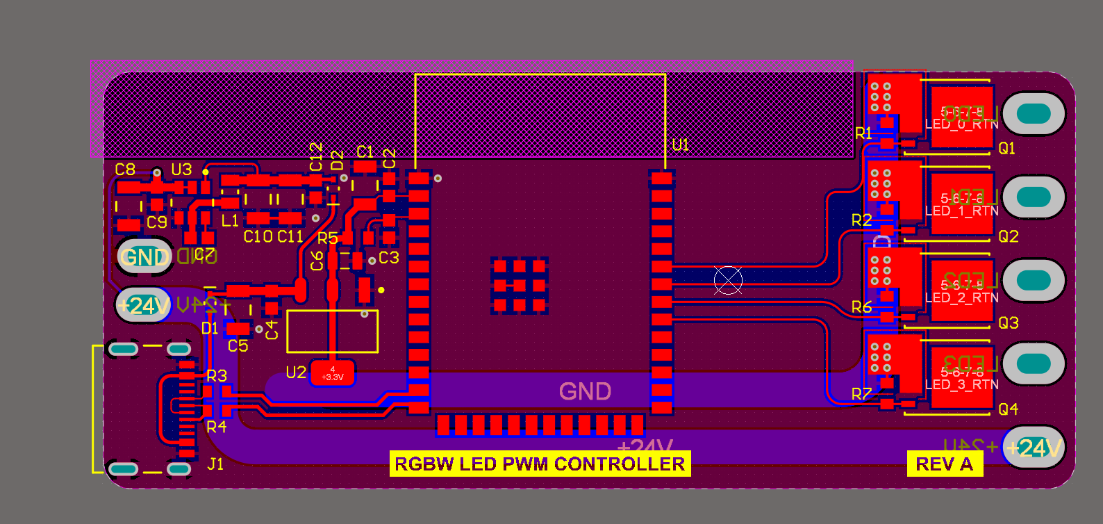
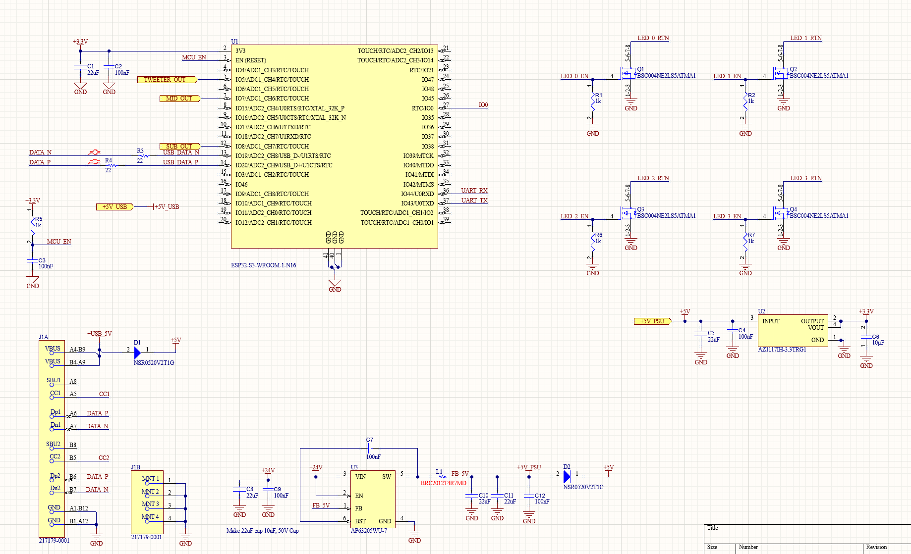
I've tried cutting the GND return trace and adding a jumper wire directly to the GND power input, I've tried adding a 470 μF bulk capacitor, and I've tried using a 10 A lab bench power supply, but the issue is still present. Maybe there's something obvious in my schematic or layout, but I'm mainly looking for advice for how to fix this.

enter image description here

enter image description here

enter image description here

enter image description here

\$\endgroup\$
1
  • 2
    \$\begingroup\$ Does anything happen if you solder more capacitance in parallel with C2? What does Vcc and 5 V look like on your oscilloscope when the PWM is running? \$\endgroup\$
    – winny
    Commented Oct 25 at 5:59

1 Answer 1

1
\$\begingroup\$

Hypothesis 1: high current from LEDs creates voltage drop across your ground, make a mess.

It's safer to put the high current input and output connectors on the same side of the board to avoid this issue.

How to test: scrape the soldermask off the ground plane on the bottom right of the board and move the 24V ground connection to this point. Also move the +24V connection to the right, so the high current no longer flows through the board. Test it.

Hypothesis 2: DC/DC mishap

No issue with the DC/DC chip choice and layout. The inductor saturation current (700mA) looks too low compared to the chip's internal current limit (3.9A max), so the chip may have trouble keeping the inductor current under control. Symptoms would be the DC-DC freaking out when the ESP32 is using a lot of current, when transmitting over WiFi.

Hypothesis 3: AZ1117 overheating.

It has no copper area to cool it, so this may occur, although unlikely, as the diode will take a chunk of the voltage drop, so dissipation in the LDO should be low. It looks stable with ceramic caps, and it's not AMS1117, so I don't think it is the culprit.

Hypothesis 4: MOSFET issues.

Perhaps you went a bit over the top on the RdsON, but at least they should stay cool. 25V MOSFETs on a 24V supply is asking for trouble. But they're not blowing up (yet) so that's not the cause. Now, there is no gate resistor, so the MOSFETs will act like a discharged capacitor, ie a short circuit seen from ESP32, until their gate capacitance charges, and it is quite substantial given the very low RdsON... Perhaps the ESP32 GPIO will object to having to output such a large current spike...

There's also the issue of switching too fast. I'm not sure it will occur here because the ESP32 output can't deliver enough current to switch this MOSFET quickly, but it it was a MOSFET with smaller capacitance... switching it too fast means the wires to your LEDs would carry di/dt in the 10-100A/µs, in other words that's a high power radio jammer.

Adding gate resistors would fix both issues. A switching time of a few µs makes a lot less noise than a few tens of ns.

\$\endgroup\$
2
  • \$\begingroup\$ I figured out the issue. My DC-DC converter gets destroyed when hot plugging my 24V supply. The converter was probably allowing the 24V to pass through, causing a thermal shutdown on the linear voltage regulator. Thanks for the help \$\endgroup\$
    – Jay
    Commented Oct 27 at 20:42
  • \$\begingroup\$ Nice catch! That's probably the voltage spike from wire inductance + low ESR input cap making a LC circuit that rings when the supply is hotplugged, peaks at double the input voltage, and kills your chip... Solutions: TVS diode to cut the peak, or electrolytic cap on the input with enough ESR to damp the ringing so the spike doesn't occur. \$\endgroup\$
    – bobflux
    Commented Oct 27 at 20:50

Your Answer

By clicking “Post Your Answer”, you agree to our terms of service and acknowledge you have read our privacy policy.

Not the answer you're looking for? Browse other questions tagged or ask your own question.