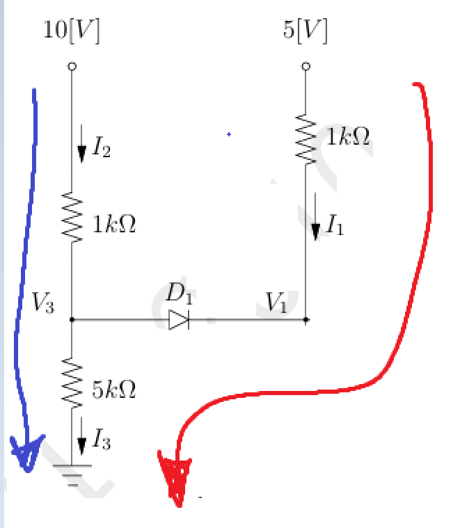
Well, the very first thing I would do to provide a quick sanity check is to treat the two resistors on the left as a voltage divider and compute the Thevenin equivalent, which is \$V_{_\text{TH}}=\frac{25}{3}\:\text{V}\$ and \$R_{_\text{TH}}=\frac{25}{30}\:\text{k}\Omega\$.
This does mean that the diode is forward biased, so that's good.
This also means that the diode current should be \$I_{_\text{D}}=\frac{\frac{25}{3}\:\text{V}\,-\,5\:\text{V}\,-\,750\:\text{mV}}{\frac{25}{30}\:\text{k}\Omega\,+\,1\:\text{k}\Omega}=1.4\overline{09}\:\text{mA}\$.
This magnitude matches the teacher's solution quite well, suggesting the fuller solution details may also be correct.
So let's look at how I'd set this up (before I bother reading what you wrote) and see where I go with it. Then I'll compare, afterwards.
Here's what I'd do:
kvl1 = Eq( 10 - i2*1e3 - i3*5e3, 0 )          # KVL, left side
kvl2 = Eq( 5 - i1*1e3 + 0.75 - i3*5e3, 0 )    # KVL, right side
kcl3 = Eq( i3, i1 + i2 )                      # KCL, at joining vertex
solve( [ kvl1, kvl2, kcl3 ], [ i1, i2, i3 ] ) # solve it
{i1: -0.00140909090909091, i2: 0.00284090909090909, i3: 0.00143181818181818}
That's pretty close to the teacher's solution, though there is slight difference in the third significant place for one of the values.
Now, I'll look at your work. Hmm....
(1) 5 - i11000 - 0.75 - i35000 = 0
I've highlighted at least one problem. Compare with my own KVL2 above. You subtracted when you should have added. Note the polarity of the diode? The anode is more positive than the cathode, when it is on. (And it is.) So you need to add that value, not subtract it.

