3
\$\begingroup\$

I have an issue with my Circuit, it looks following: enter image description here

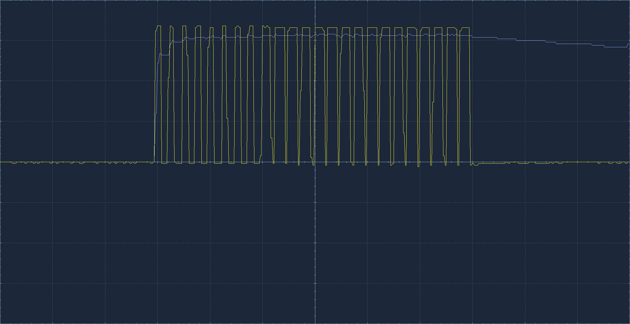
The circuit consists of a current limiting resistor the Schottky Diode NSVR0170HT1G and an ESD Diode in parallel. A MCU is driving the PWM Signal with a Frequency of around 1 MHz. The Diode is supposed to be there to secure the MCU from being destroyed if somebody accidently applies a high voltage to the "OUT_LED_COM Pin 34". The signal I get at the output looks like this (yellow desired, blue actual, Scale: 5 us, 1 V): enter image description here
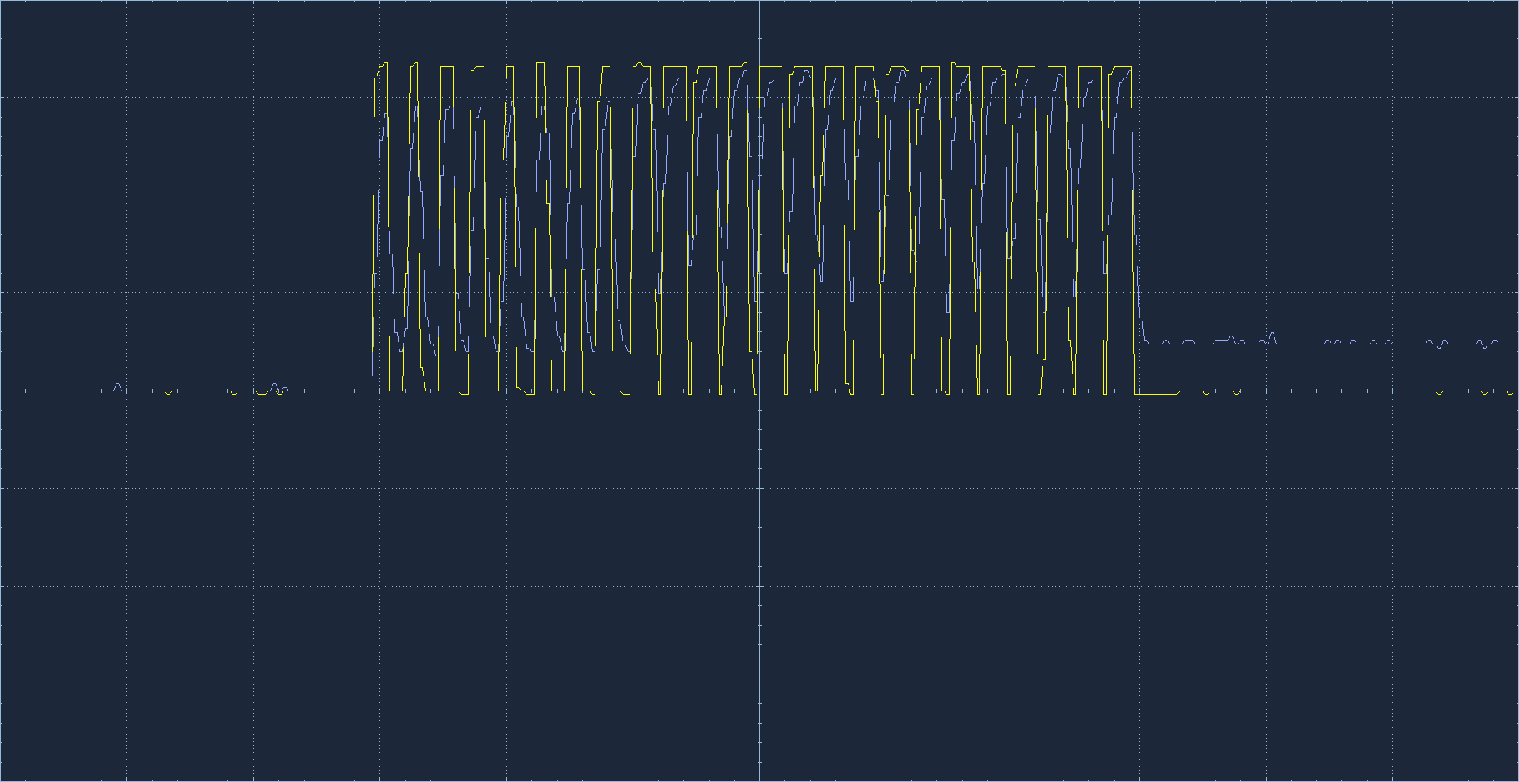
I tried other Diodes like the B560C-13-F which already look a little better: enter image description here
I also tried adding a 1n Capacitor in parallel to the NSVR0170HT1G which also helps make the signal look better but still its very slurred: enter image description here
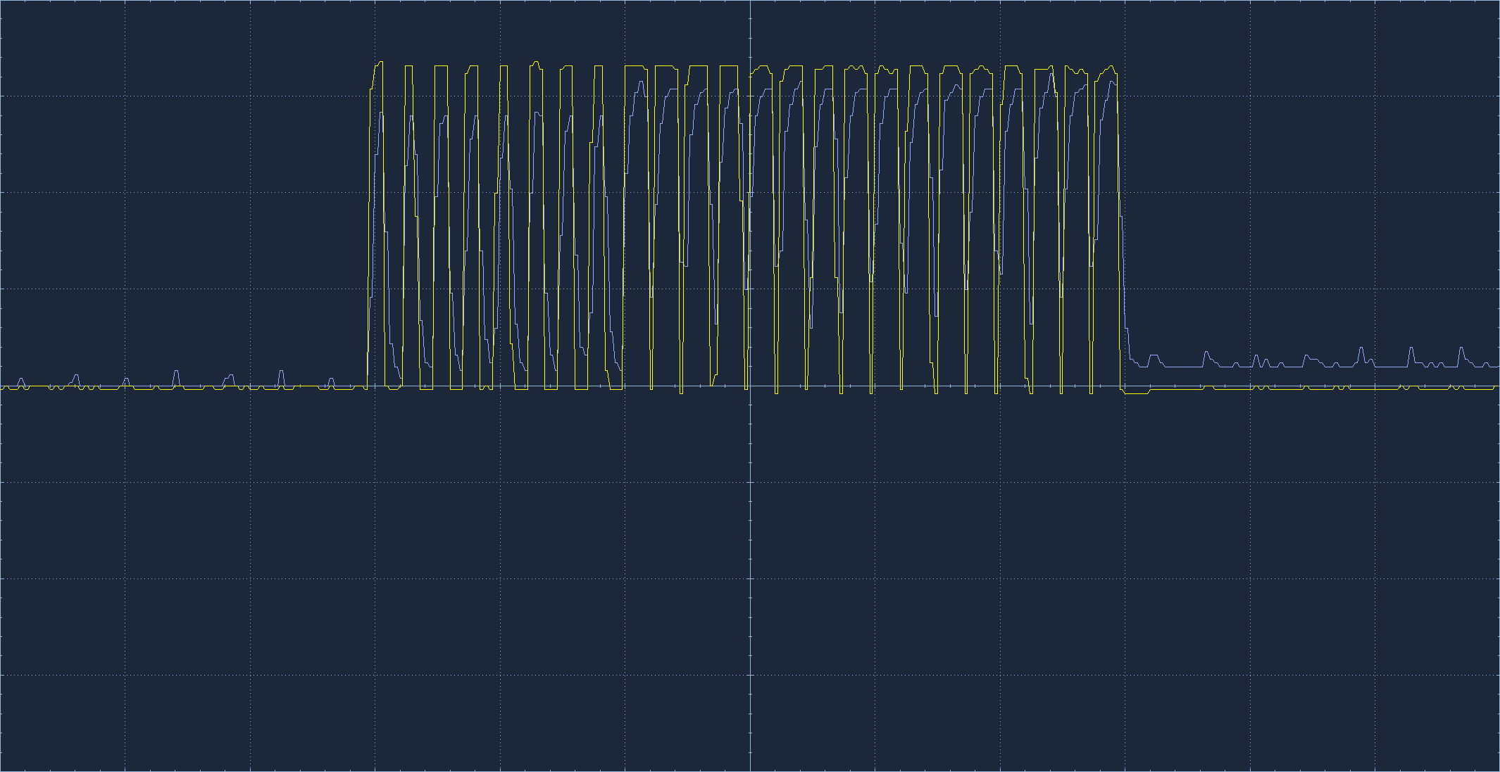
Probably I get this problem because the switching time of the NSVR0170HT1G is too slow right? What I don't understand is, why a parallel capacitor helps with making the signal better?

Also the capacitor can't fix the problem fully. Do you have any idea on how I can better the output signal with or without changing the Diode? I would really like to understand the background, why I get this issue.

I hope you can help me with that!

\$\endgroup\$
0

2 Answers 2

3
\$\begingroup\$

The driving signal from the MCU is unable to pull the output low because of D7. D33 has a capacitance of 350pF according to the data, and is very high impedance, so there is no way for that 350pF cap to discharge.

If you put a pull down resistor of (say) 10k across the output, you should see the expected signal.

(Probably you are using a scope with with 1M or 10M input impedance to look at the signal, that gives a 5CR time of either 1.75ms or 17.5ms, much too slow to allow the voltage to drop with a 1MHz signal. I just worked out that to discharge 350pF in 100us you would want not more than 56k pull down.)

\$\endgroup\$
7
  • 1
    \$\begingroup\$ Hello, thanks a lot, that explains! When I add a capacitor of 100 nF in parallel to the D7 and reduce the resistance of R21, the result is getting even better, why is that? With the scope you mean that it basically has no effect on discharging the 350 pF right? \$\endgroup\$ Commented Nov 14 at 17:12
  • 1
    \$\begingroup\$ the scope has SOME effect, it is effectively a resistor of (probably) 1M or 10M to ground. But the resistance is just too high to do much good at that frequency. The parallel cap looks like a low impedance at 1MHz so the output driver is more able to to pull the signal low - but it is not really a good approach to solving the problem, as the uC probably does not r5eally like to see a complex load like that. If this does not make sense to you, revise your basic on CR circuits with AC. \$\endgroup\$
    – danmcb
    Commented Nov 14 at 17:50
  • \$\begingroup\$ Hello, I get that the cap is a low impedance to a high frequency signal but why wouldn't my uC like a load like that, what could be the possible issue? \$\endgroup\$ Commented Nov 15 at 8:25
  • 1
    \$\begingroup\$ probably none, but a logic output on a uC generally expects to see a load that is mostly resistive. Also that cap will inevitably compromise your transient protection, which was the point of D7 in the first place. The problem is more easily solved by adding a load resistor. \$\endgroup\$
    – danmcb
    Commented Nov 15 at 8:27
  • \$\begingroup\$ That is true, I totally forgot about the purpose of the Diode in the first place. Thanks again for your help! \$\endgroup\$ Commented Nov 15 at 8:35
3
\$\begingroup\$

A diode can only drive the current one way. The only AC connection to discharge the parasitic capacitance on the load side of the diode is the parasitic capacitance of D7 itself.

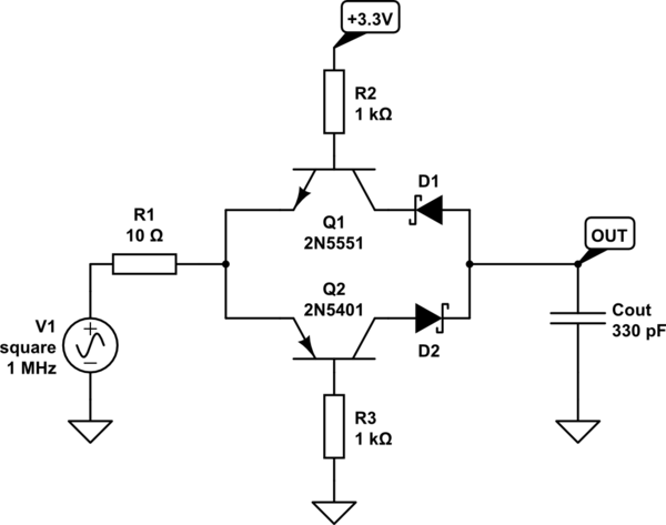
Instead of unipolar protection, we can use two diodes, and high voltage clamps Q1 and Q2. The V(CE) of those transistors determines how high of a voltage the circuit can withstand. I have built circuits based on similar principle to protect inputs of a milliohmmeter from connection to mains.

schematic

simulate this circuit – Schematic created using CircuitLab

Cout represents the parasitic output capacitance of the transient suppressor diode. That diode only needs to clamp at say 75% of lowest V(CE) of the two transistors. Perhaps it will have lower capacitance then?

In the simulation above, R1 represents the output impedance of an MCU GPIO pin set to high current mode. In the real circuit, there'll be no resistor there.

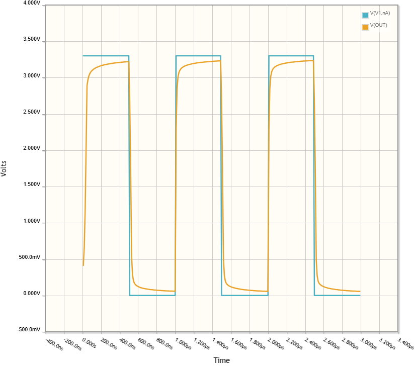
enter image description here

\$\endgroup\$
3
  • \$\begingroup\$ Hello, thanks for the reply! That's definetly an option I should look into. For now it doesn't help me a lot because I can't change the circuit too much. A PCB was already made with the circuit I posted and I need to try to fix it with adding/removing some small components. \$\endgroup\$ Commented Nov 15 at 8:21
  • \$\begingroup\$ @TErlieskttainvo Why oh why would anyone just lay out a PCB without testing the building blocks used on a breadboard if used for the first time? It makes no sense. I guess a lesson for next time. Also, PCBs are dirt cheap. You could test this circuit on a breadboard and order another PCB. Or put the fix on a little "daughterboard" that can be glued to empty room after removing the original circuit's components from the PCB, and enameled wire used to connect it. Anyway, it is a common theme here on SE where people who never built some circuit lay it out and oops "we can't change it". Madness. \$\endgroup\$ Commented Nov 15 at 13:10
  • 1
    \$\begingroup\$ Basically, what you have done with that PCB was a prototype, not a production design. It was never tested, it's a prototype. By the very definition! Maybe it's the management that thinks "oh we have a pcb, get it to work and we make more"?? It really was a prototype. It can't go into production as it is. Get another one made. That's how prototyping works. Lesson learned. \$\endgroup\$ Commented Nov 15 at 13:11

Your Answer

By clicking “Post Your Answer”, you agree to our terms of service and acknowledge you have read our privacy policy.

Not the answer you're looking for? Browse other questions tagged or ask your own question.