7
\$\begingroup\$

I am interested in any feedback or caveats regarding the following capacitance measurement method before I begin setting it up.

For an experiment, I have come across the need to measure and track the spacing between two samples, with resolution of 0.1 mm or better. Due to the constraints of the rest of my setup, after a little bit of research, it appears to me that a capacitive measurement method is most suitable to infer the spacing.

Consider the following simplification as the goal:

I would like to measure/track the distance between 2 copper plates (each 2cm X 2cm) that essentially form a big capacitor.

Note: AD7746 below is a 2-channel, 24-bit sigma-delta Capacitance-to-digital converter
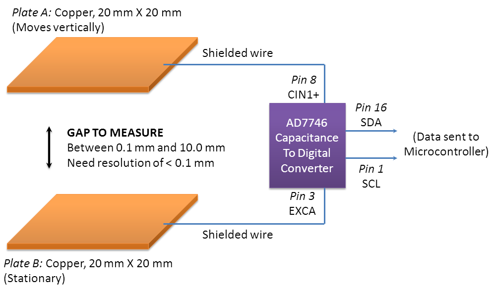
illustration

  • The idea: Starting with \$C=\varepsilon_0\varepsilon_r \frac{A}{d}\$, where the plate area the dielectric of air are constant, it's of course true that the measured capacitance is inversely proportional to distance. So I could first take some calibration data, and using that, adjust accordingly to infer the distance from any measured capacitance value.

  • The measurement method: Given my fairly stringent requirement of 0.1 mm resolution or better, I plan to go for a precise measurement by using Analog Devices capacitive measurement IC AD7746.

What things should I be careful about to get as clean a measurement as possible, or what aspects can I improve upon? Could the above get me my desired resolution, or is it prone to error sources that I'm not seeing?

One possible improvement is: I was thinking, since AD7746 has two channels, I could even use the extra channel to also simultaneously measure a separate pair of completely fixed/reference plates, and use that to nullify any temperature or EMI effects. Hmm, not sure how important those factors are...

UPDATE (more detail): A bit more about my setup, and what constraints exist: The experiment involves a larger sample that is directly above, kissing the top plate. The sample is about 75mm X 75mm (non-metallic) and it sort of crushes the top plate down during the vertical motion.

As a result, there is no scope for placing any sensors vertically parallel to the Y-axis motion. Any sensing of the vertical displacement/gap would have to be accomplished either horizontally, or with parts mounted on a board in the position of the bottom plate.

With that said, the top plate was added just for my proposed way of measurement, and is not strictly necessary. My primary goal is to measure how far away my aforementioned 75mm X 75mm sample ends up vertically from the bottom.

UPDATE (Measurement result): I ran a quick test on the capacitive measurement, and I was able to distinguish the capacitance data fairly clearly at about 0.2 mm steps in the displacement. The noise I'm getting in the capacitance measurement is, as of now, too large to get better resolution than that. I am trying to vary a few things to see if I can improve the SNR in the capacitance measurement.

\$\endgroup\$
11
  • \$\begingroup\$ Thank you RedGrittyBrick for helping to add the image to my question. \$\endgroup\$
    – sasha
    Commented Jul 3, 2013 at 12:53
  • 2
    \$\begingroup\$ Your plate dimensions are small relative to the maximum spacing, so you will have significant nonlinearities arising from field fringing effects at their edges. This can be corrected for, but you'll also have to beware of any other conductive or dielectric objects nearby. \$\endgroup\$
    – Dave Tweed
    Commented Jul 3, 2013 at 13:28
  • \$\begingroup\$ Why can't you use an optical encoder? Perhaps even a simple optical mouse... \$\endgroup\$
    – Dave Tweed
    Commented Jul 3, 2013 at 13:34
  • \$\begingroup\$ @Dave Tweed: Yes, the plate sidelength is only about double the size of the maximum plate-spacing I expect. When you say nearby, how nearby would any other conductive material have to be to have a significant effect? Do you think about 2 cm of clearance around the plates is sufficient to ensure induced errors of less than 1% in the capacitance? \$\endgroup\$
    – sasha
    Commented Jul 3, 2013 at 13:35
  • 1
    \$\begingroup\$ You have described virtually nothing about the physical constraints of your setup. For the mouse, I was thinking that an optical mouse could be looking at a reference pattern on a vertical side of the moving object (rather than the horizontal bottom), and detecting lateral displacement rather than range. \$\endgroup\$
    – Dave Tweed
    Commented Jul 3, 2013 at 15:35

3 Answers 3

3
\$\begingroup\$

As Dave Tweed already mentioned, the fact that the maximal separation is comparable to plates' dimensions makes this setup problematic. You may get accurate estimation of the distance while the plates are close together, but this setup won't work for the whole range.

Dave suggested that these nonlinearities may be accounted for, but I don't see how this can be achieved, satisfying the required accuracy, without very complicated calculations.

However, since you're going to use microcontroller, you may try the following trick: perform initial mapping of distances to capacitance, store this data in microcontrollers memory (assuming it is sophisticated enough) and use the stored data as a look-up-table to map the measured capacitance back to distance.

As to the required clearance, it depends on which objects may be present in the vicinity of your setup. Consider shielding it with conductive screens.

\$\endgroup\$
2
  • \$\begingroup\$ @Vasily: Gave the lookup table idea a try; Updated my question with my 1st measurement result. What do you mean by shielding it with a conductive screen? I did a google search on conductive screen, and don't see any relevant results. \$\endgroup\$
    – sasha
    Commented Jul 5, 2013 at 4:44
  • \$\begingroup\$ @sasha, I meant to say that you can place the whole setup into a conductive "box" which is held at constant potential (usually grounded). In this case, the capacitance will be independent of either the objects or the radiation outside the box. However, in light of additioanl information you provided, I see that this shielding will require a lot of space in your design. You mentioned "noise in capacitance measurements" - do you refer to the difference in successive measurements while the plates do not move, or something else? Did you try averaging your measurements? \$\endgroup\$
    – Vasiliy
    Commented Jul 5, 2013 at 7:40
4
\$\begingroup\$

You might consider a geometry that varies the OVERLAP of the plates instead of distance. Your capacitance will vary linearly with the overlap. C varies as 1/d, so as it stands, your sensitivity at the far point will be cruddy. Even changing to overlap, I wouldn't count on 1% accuracy.

Consider the other options already mentioned, or an LVDT.

UPDATE: As a followup, many measurements such as this are improved by a push-pull arrangement. If you can work this out using TWO capacitors, where one gets bigger at the same time and rate as the other gets smaller, sensitivity and linearity will both improve.

\$\endgroup\$
4
  • \$\begingroup\$ I am seeing if the geometry can be rearranged; the Updated tip sounds interesting. Especially given that this chip already has two channels. \$\endgroup\$
    – sasha
    Commented Jul 5, 2013 at 4:25
  • \$\begingroup\$ Regarding LVDT: The problem is that the rest of my setup is such that there is a larger, wider mass that sort of "crushes" the top plate down -- In other words, I cannot VERTICALLY place any LVDT/sensor along the walls of the movement. The LVDT, no matter how tiny, could only be placed horizontally. So, if I were to try the LVDT approach, do you see any way to resolve this conundrum? \$\endgroup\$
    – sasha
    Commented Jul 5, 2013 at 4:27
  • \$\begingroup\$ There appear to be some really neat, miniature-sized LVDTs, and LVDTs have a proven record for this sort of linear movement, so I'm trying to see how can I convert the vertical movement to a horizontal one somehow. Perhaps I could make the top plate 45-degree-angled, so that it's like an alligator clip pressed down, and somehow have the motion translate to a horizontal displacement? Or maybe hook the draw wire of a string pot to the top plate and run the wire through the LVDT? \$\endgroup\$
    – sasha
    Commented Jul 5, 2013 at 5:03
  • \$\begingroup\$ If you have a string pot in the arrangement you wouldn't need the LVDT. As to whether you can adapt your system to the LVDT, that just depends on your mechanical creativity. \$\endgroup\$ Commented Jul 5, 2013 at 10:58
3
\$\begingroup\$

Consider this as an alternative to using capacitance at the greater distances.

Use an optical communications laser of the type that has a very specific divergent beam (a lot of them are designed like this to be suitable for fibre optic interfacing). It "sprays" its light output onto a fractional surface of a sphere at a certain angle. The further you are from the laser, the less is the incident power received per square mm (such as from a receiving photo transistor). EDIT A lot have in built photo-diodes so you can accurately control the laser output light power.

The photo transistor will have an active surface area which it can receive light. This of course is constant irrespective of the distance from the laser, therefore it receives a weaker signal as the two are moved further apart.

You'd need to modulate the laser with a square wave so you can use this to filter-in the photo transistor signal to prevent dc effects like sunlight ruining results.

In may not work that effectively up close (<2mm) because alignment errors then become a really big issue but, up-close your capacitance idea works best from what I can see. Maybe use both.

\$\endgroup\$
1
  • \$\begingroup\$ Thank you. The only problem for the optical idea is that there is not enough space. (I've updated the question with a bit more detail about my setup.) There is a large sample directly above the top plate which would obscure any interaction with a beam-source placed outside the very narrow space that exists. So, preferably, the measurement would have to be internalized within the illustrated space above. I do like the idea of square wave modulation of the laser; have to give that a try on a future project. \$\endgroup\$
    – sasha
    Commented Jul 5, 2013 at 4:42

Your Answer

By clicking “Post Your Answer”, you agree to our terms of service and acknowledge you have read our privacy policy.

Not the answer you're looking for? Browse other questions tagged or ask your own question.