6
\$\begingroup\$

I am working on a circuit that controls the power to another circuit.

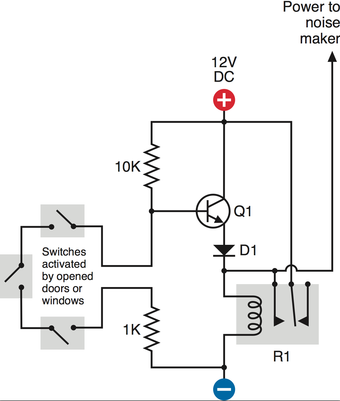
As you can see in the schematic, when the switches are closed, current runs through the circuit, and no positive voltage is applied to the base of the transistor. However, when the switches are open, a positive voltage applied at the base allows current to flow through, switching on the relay and powering the "noise maker."

My problem: I cannot seem to get the transistor to switch on when I open the switches. I tried checking the current flowing through the transistor, but simply touching the leads to collector/emitter causes the transistor to switch on.

So I know all the components are correct and that the rest of the circuit is working.

How can I solve this problem? I understand that for this NPN transistor, I need to apply voltage ~0.6 volts greater at the base than that at the emitter. Also, the voltage at the collector must be more positive than that at the base. If this is my problem, how can I adjust these values?

Edited to add part details: - Circuit includes 2N222 Bipolar Transistor, 1N4001 Diode, HLS-14F3L-DC12V-C Relay

enter image description here

\$\endgroup\$
4
  • \$\begingroup\$ I've just included your image directly, now you have a reputation above 10 you can do that yourself on future questions. \$\endgroup\$
    – PeterJ
    Commented Jul 16, 2013 at 3:07
  • 1
    \$\begingroup\$ No, the voltage at the collector need not be more positive than at the base. The opposite is the case at saturation, which you want in a switching application. \$\endgroup\$
    – Kaz
    Commented Jul 16, 2013 at 3:23
  • 1
    \$\begingroup\$ Part numbers and links to datasheets for your transistor and your relay would help get a good answer to this question. \$\endgroup\$
    – The Photon
    Commented Jul 16, 2013 at 3:36
  • \$\begingroup\$ Are you sure you have it wired up correctly? I'm working on the same project (I'm assuming this is Experiment 15 from Make: Electronics) and had problems getting to work at first. I thought it was because there wasn't enough power going to the relay, but turned out to be a wiring issue. Could you post a pic of the circuit on the breadboard (if you're still on the breadboarding stage)? \$\endgroup\$
    – Chaulky
    Commented Jan 15, 2014 at 4:15

3 Answers 3

2
\$\begingroup\$

With the switches closed you would be trying to turn the relay on. As your circuit stands it doesn't work because the emitter voltage could never rise enough to power the relay. Even if it could it means you would be powering the relay most of the time - a waste of energy. Also, if the door/window was opened momentarily as soon as it was closed the alarm would stop.

enter image description here

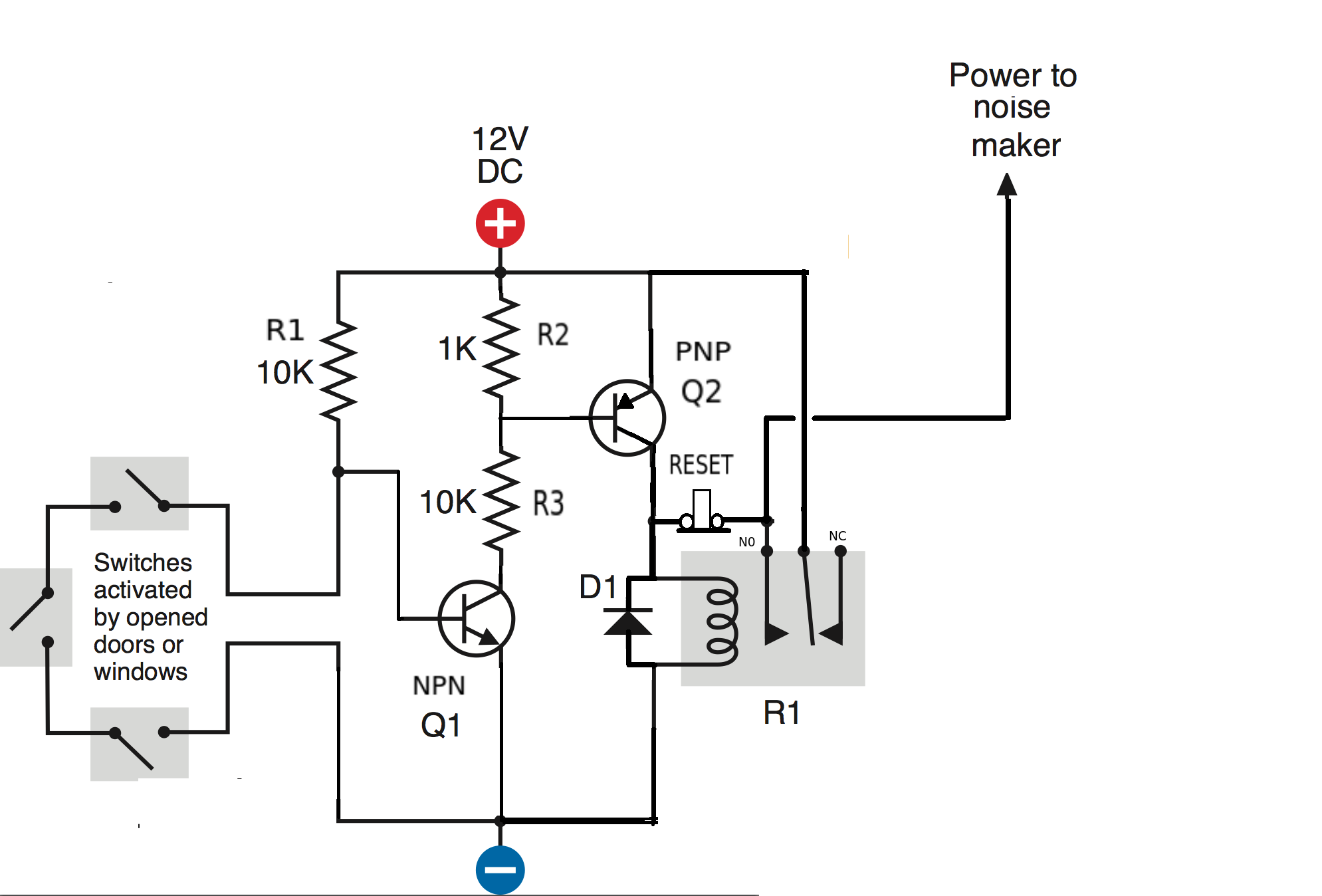
By adding a second transistor Q2 (PNP) and a push to break switch you can improve your circuit (and get it to work).

The closed switches turn Q1 OFF (base connected to ground). As there is no current flowing through the 1K resistor Q2 is also OFF. No current can flow through the relay. The only current to flow is through R1 so the circuit will only draw 1.2mA.

If any switch is opened Q1 is turned ON and draws a current through R2 and R3. The voltage across R2 will be clamped by the emitter-base of Q2 to about 0.6V and will turn Q2 ON. With Q2 turned ON its collector current will turn the relay ON.

The diode (D1) is connected across the coil of the relay to prevent damaging Q2 from the back emf when the relay is turned OFF.

The relay switch over and closes the circuit between its common and normally open contacts.

The reset switch (push to OPEN) keeps the relay turned ON even if the door/window switches are closed after opening. It LATCHES the relay. Just omit the reset switch if you don't want this feature.

\$\endgroup\$
2
\$\begingroup\$

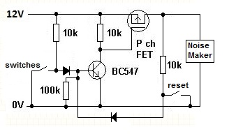
Why use a relay when a small P channel FET will do: -

enter image description here

When the switch(es) goes open circuit the BC547 gets base drive and pulls the P channel FET's gate to ground turning that device on which activates the noise maker. The action of activating the noise maker also feeds a signal back to the BC547 base keeping it turned on (should a latch circuit be needed). A reset switch will turn off the FET providing the switch open problem is cleared.

\$\endgroup\$
1
\$\begingroup\$

The circuit as drawn is effectively configured as an emitter follower, with the relay coil acting as the emitter resistor. That means that the voltage at the emitter will follow the voltage at the base (minus one diode drop of approximately 0.6V).

In order for the relay to turn on in this configuration, the base must be brought one diode drop higher than the "pull-in" voltage of the relay coil. As a general rule of thumb, the collector current (which flows through the relay coil) is about 100 times the base current. This rule of thumb allows you to estimate the required base current if you know the amount of current that is supposed to flow through the coil when the relay is on.

The base current is a problem: Suppose you have a 12 Volt relay with a 600 Ohm coil resistance. That requires 20 mA through the collector, which means 0.2 mA through the base. But since the power supply is only 12 Volts, even connecting the base directly to the 12 V rail doesn't help: the two diode drops (one for the base-emitter and one for the diode) leave the emitter at 10.8 V, probably only barely enough pull in the relay.

If you put a resistor between the base and power supply rail, it gets even worse: pulling even 0.2 mA through a 10k resistor (like in your schematic) results in a 2 Volt potential across the resistor. So now your base is at only 12 V - 2 V = 10V, and the relay is 1.2 V below that, or 8.8 V. You're supplying only about three quarters of what the coil needs!

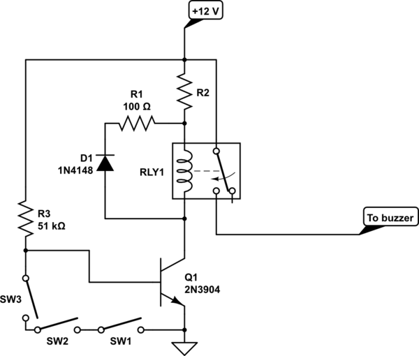
It's possible to make the circuit work using almost no extra parts, and I've included a schematic in this edit to help show what I mean. The basic difference is to switch the position of the transistor and relay, so that the transistor pulls down the negative side of the relay instead of pulling up the positive side. This is called a common-emitter configuration.

The circuit acts as (I think) you want it to, and the only new parts are two resistors: R3 and R1. You could use the original 10k resistor in place of R3, at the cost of slightly increased current consumption (1 mA vs. 0.2 mA) when the switches are all closed. R1 and D1 provide a path for coil current when the transistor T1 turns off. You may be able to use the original 1 k resistor for R1 if your transistor can withstand -10 V between the collector and emitter (you'll need to read the data sheet to find out). R2 is optional (you'll notice that I didn't specify a value), and depends on the specifications of your relay. If your relay is meant to be driven directly from a 12 V source, then R2 may be omitted. Any time one or more switch opens, the relay closes the normally-open contact.
schematic

simulate this circuit – Schematic created using CircuitLab
\$\endgroup\$
3
  • \$\begingroup\$ Sorry dude - my mistake - I've deleted my stupid comment \$\endgroup\$
    – Andy aka
    Commented Jul 16, 2013 at 10:45
  • \$\begingroup\$ Hey Nick, thanks for the suggestions. If I switch the transistor and the relay, wouldn't this mean the relay would have to constantly be in an "always on" position? The reason I don't have this setup is that the relay will take significant power, and may get hot over time. What do you think? Is there a way to get around this? \$\endgroup\$
    – Victor
    Commented Jul 17, 2013 at 1:16
  • \$\begingroup\$ Hi Victor, I added a schematic and tweaked my suggested circuit very slightly so that the relay is off when the switches are closed \$\endgroup\$
    – nick g
    Commented Jul 24, 2013 at 4:34

Your Answer

By clicking “Post Your Answer”, you agree to our terms of service and acknowledge you have read our privacy policy.

Not the answer you're looking for? Browse other questions tagged or ask your own question.