I don't have an LCR meter and wanted to learn how to use a fast edge pulse generator and an oscilloscope to do capacitance measurements as an academic exercise.
In W2AEW's videos, he builds a simple fast edge pulse generator using a 74AC14 hex Schmitt trigger (inverting) and demonstrates how to use it for capacitance and inductance measurements as well as a time-domain reflectometer.
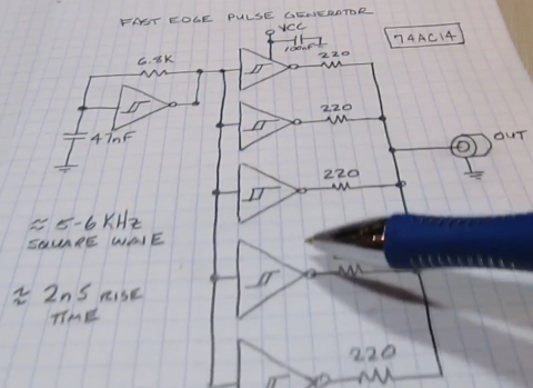
I've built this up on a breadboard, but am getting some different results.
I am measuring the input and output of the first Schmitt trigger with a 100MHz digital oscilloscope, with the same value components (6.8kΩ resistor; 0.047μF capacitor) at 5V DC.
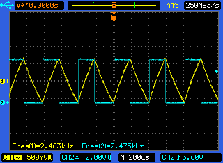
First, the frequency is about 2.5 kHz, not 6 kHz as in W2AEW's example. I'm not sure what is causing the substantial difference. But for this application, the frequency is not as important, so I haven't worried about it.
Second (and what this question is about), when I look closely at the rise time of the square wave output, I am measuring something like 60ns, instead of <5ns as expected.
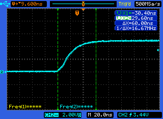
I realize that measuring something as fast as 2ns with a 100MHz scope is not ideal (I assume I would want something like 500MHz to obtain more detail), but I didn't expect such a difference.
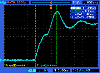
W2AEW's edge, measured with a 350MHz analog scope is quite different looking:
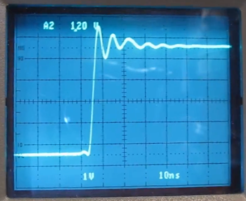
Is it possible there's something wrong with my circuit, or do I simply not have a fast enough scope to measure such fast edges?
Edit/Update:
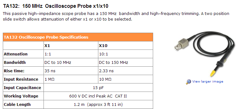
Per Oli Glaser's answer, the reason for the delay is that the probes were set to 1x rather than 10x, and limiting bandwidth, possibly as low as 10MHz. By setting the probes to 10x, the waveform immediately starts to resemble what it should (~13ns). The extra delay and capacitance is probably because I am using a breadboard and some unshielded jumpers to connect to the oscilloscope probes.
Here's the resulting improved display:
