2
\$\begingroup\$

Given the below H-Bridge, how do you calculate the current through the conduction paths? This particular IC, the L298, has a per-bridge limit of 2A - so I know the upper limit.

If I were to place a motor across the leads then, based on the motor's load, I would have a rough idea via the datasheet of that motor.

But what if I were to place a resistor across OUT1 and OUT2, or short them?


If shorted:

The entire supply Vs would appear across two transistors. Would it simply be distributed as Vs/2 per transistor? How would you calculate the associated current?

Does the answer lie withing this characteristic?: enter image description here

So, does this mean that if the transistor has 400mV across the collector-emitter junction thn the current will be saturated at 150mA? So that is, with two of these transistors and OUT1 and OUT2 shorted together, terminals in the below bridge would have 150mA through them since the supply (if the supply Vs is greater than 800mV) would be across their junctions?

How would you calculate the current if the terminals were not saturated - or do transistors in this application always operate in saturation mode?


If OUT1 and OUT2 are tied together with a resistor:

If the supply is greater than 800mV, will the transistors automatically be in saturation mode with 150mA of current draw (for the 2n2222)? If so, the voltage across some resistance R connected across the terminals of OUT1 and OUT2 would then be 150mA*R.

And consequentially, would the voltage across the transistors would be Vt = (Vs-150mA*R)/2?
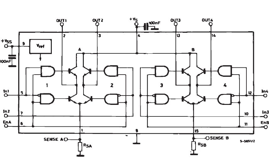
enter image description here

Basically, what I am asking is how to calculate the current in the following two configurations:
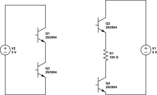
schematic

simulate this circuit – Schematic created using CircuitLab

Assuming that transistors are biased with base current as shown in the above IC schematic. How would you calculate the voltage across the resistor and the current in either case?

\$\endgroup\$

1 Answer 1

1
\$\begingroup\$

I had to read this question several times to try and get my head around what is being asked.

(1) Forget about the saturation voltage of a 2n2222 transistor - this has nothing to do with the operation of the H bridge circuit.

(2) The voltage is not ACROSS the output (bridge) transistors. It is measured between OUT1 and OUT2 and will be just less than the supply voltage.

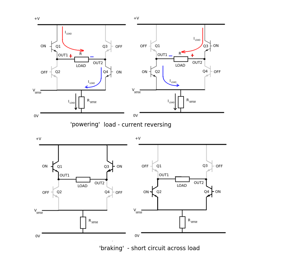
They operate in opposite PAIRS. One transistor connects the load to the POSITIVE SUPPLY and the other connects it to the GROUND (0) SUPPLY through the current sense resistor. In other words they act as SWITCHES (fully saturated transistors).

enter image description here

What appears ACROSS the load is almost the full supply voltage. The circuit can switch the DIRECTION of the voltage by using the opposite PAIR of transistors in the bridge output.

(3) The maximum load current supplied through the L298 to 2A per bridge. You can parallel connect the outputs to give a maximum of 4A but be sure to connect the inputs the correct way around.

The CURRENT output depends on the LOAD. In the case of a SHORT CIRCUIT the output current should be limited to 2A per bridge using the SENSE pin outputs and external circuit.

The current for any particular load can be calculated using OHM's LAW I = V/R where V is the output voltage (OUT1 -> OUT2) volts from the bridge and R is the load resistance in ohms.

\$\endgroup\$
4
  • \$\begingroup\$ I understand the idea behind the H-Bridge, I was just wondering about the voltage and current given various ways of wiring OUT1 and OUT2. I actually have one of these chips and with a supply of 4.6V, I get only 2.5V across a 3V DC motor (connected to OUT1 and OUT2). The other 1.6V is across the transistors - which is why I ask this question. I was curious to see how the calculations were changed with regards to a shorted connection between OUT1 and OUT2, or a a connection between them with a resistor. \$\endgroup\$
    – sherrellbc
    Commented Aug 18, 2013 at 20:24
  • \$\begingroup\$ I measured OUT1 to be 3.3V and OUT2 to be 0.8V. Further, the datasheet notes that the no-load operating current of my motor is 300mA. So, from that I can calculate the 2.5V/300mA = ~8 ohms. For simple coil windings that sounded about right, but I was not quite sure. \$\endgroup\$
    – sherrellbc
    Commented Aug 18, 2013 at 20:33
  • \$\begingroup\$ "With a SHORT CIRCUIT this will be 2A per bridge." - that is not true. The chip will not limit the current, you must do that! \$\endgroup\$ Commented Aug 19, 2013 at 7:33
  • \$\begingroup\$ @WoutervanOoijen I stand corrected, the output voltages from SENSE A and SENSE B should be used to limit the current to the safe value of 2A per bridge. \$\endgroup\$ Commented Aug 19, 2013 at 11:08

Your Answer

By clicking “Post Your Answer”, you agree to our terms of service and acknowledge you have read our privacy policy.

Not the answer you're looking for? Browse other questions tagged or ask your own question.