Followup to my previous question.
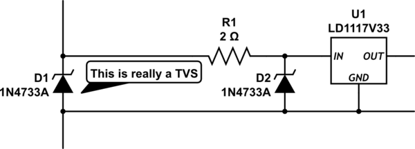
I'm designing a product powered from a 5V supply that feeds it into a TLV1117LV33 LDO. Typical current draw for the project is less than 500mA, but the regulator is cheap and stable with ceramic output caps so I like it so far. Anyway, I was advised in the previous question to put some ESD and transient protection on the Vin line, which makes sense to me, so the solution I'm thinking of is a PTC polyfuse in series, followed by a standard unidirectional TVS diode to ground.
However, all the diodes I've looked at (eg Littelfuse SP1003, Vishay GSOT05C) have quite a high clamping voltage. I understand that this is standard, ie that the maximum clamp voltage of a TVS diode will be a lot higher than its max reverse standoff. I'm also aware that lower clamping voltage and lower dynamic resistance is considered a figure of merit for TVS diodes.
However, my regulator's safe operating input range is up to 5.5V (6V absolute max). These diodes have 5V reverse standoff and typically ~7V clamping voltage at 1A (~12V at 30A). That's gonna fry my regulator easily! I've seen devices with lower clamping voltages, but when I say "lower", I mean 10V as opposed to 12V (at 30A). How do I reduce the clamping voltage so that, if an inductive transient appears on my 5V rail (or something similar), my regulator will survive?
Devices like MOVs seem to have even higher clamping voltages, so as far as I can tell, that's not a superior solution. I've also heard a bit about multi-stage ESD protection, but no advice on how to do it. Am I overthinking things?

