0
\$\begingroup\$

I have connected pin 2 to pin 3, pin 4 to pin 5, and pin 6 to pin 20.

Can someone please tell me if this is the correct wiring for loopback testing a parallel port?

Ia am using BurnInTest 7.1 Pro by PassMark Software for the test. Is this the right software for this job? This is the error I receive.

Corruption. Data received didn't match data sent. Check plug is connected.
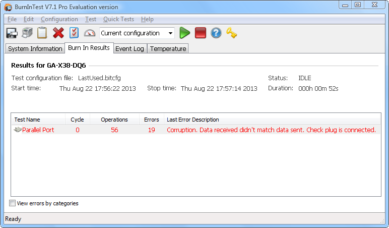
BurnInTest 7.1 Pro

The image above shows the program window 52 seconds into the test.
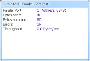
test status

The image above shows the status window 1 minute and 47 seconds into the test.

As you can tell by the images posted above, there is something wrong. How is it possible to send 40 bytes and recieve 80 bytes? I mean how can you receive twice as much as you send? This makes no sense to me. Does it make sense to you? You can see that the number of errors shown in this window is 39, which is more or less the same amount redundant data that was received.

80-40=40≈39

Can I trust these results? I have used the same program to loopback test a serial port and it did, and after 15 minutes of testing it gave me a big "PASSED" message in green letter. So I know it works for serial port testing. But does that make it trustworthy/reliable for parallal port testing?

Update


A DB25 connector can be used either for parallel communication or for serial communication. A DE9 connector can only be used for serial communciation. My mistake here was that I wired a DB25 connector for serial communication, instead of parallel. After rewiring the loopback test passed flawlessly.

See the answer below for the proper wiring of a DB25 for parallel communication.

Here are some images that show the same test being done with the proper parallel wiring. I have taken these screenshots with respect to the elapsed time of the previous ones, so you can compare them.
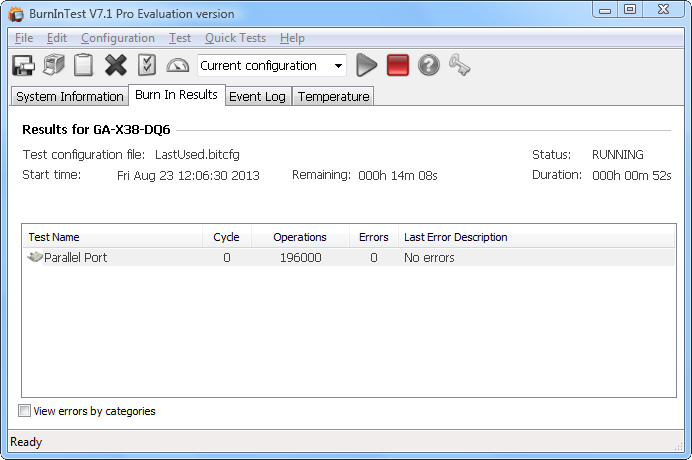
second test - main program window

Main program window, 52 seconds into the test.
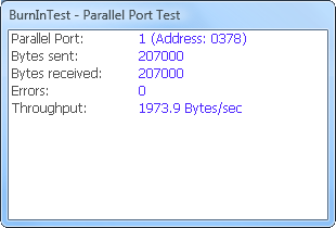
second test - test status

The status window, 1 minute and 47 seconds into the test.

Passing the test...
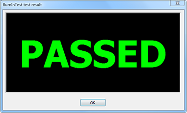
test passed - test result window

The test result window.

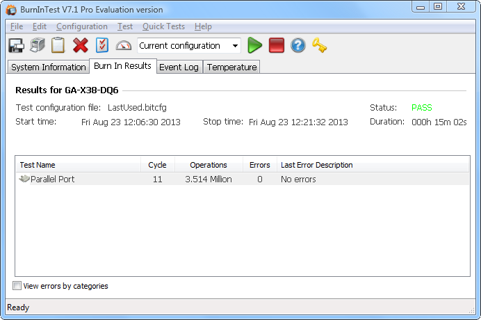
test passed - main program window

Main program window showing test duration, number of cycles, operations and result.

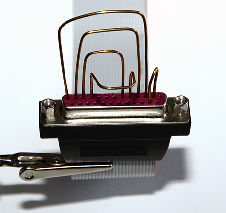
The DB25 connector...

Here's a picture of the connector. It's a female connector. This made jumpering harder for me.
db25 connector

I didn't have a proper, insulated wire with the right size. So I used a 1.0 mm diameter brass wire instead. It's a good thing it's sturdy and yet soft enough for easy bending. I made sure not to touch any adjecent conductor. It's hard to find electrical wire with the diameter of 1 mm, they are rare. This 1 mm was a perfect fit. It can be slightly thicker, but not less than that. You can use a paper clip, a.k.a. "paper clip test", but it's a bit sturdier (thicker) and hard to work with.

\$\endgroup\$
9
  • 2
    \$\begingroup\$ Your loopback arrangements are intended for RS232 serial signals through a DB-25 connector. \$\endgroup\$ Commented Aug 22, 2013 at 16:59
  • \$\begingroup\$ @RedGrittyBrick Yes, that was the problem actually. The emphasis needs to be put on "serial" here. A DB25 connector can be used either for serial or parallel communication. While a DE9 connecter can only be used for serial communication. My mistake was that I wired a DB25 connector for serial communication, instead of parallel. A beginners mistake. Thanks! \$\endgroup\$
    – Samir
    Commented Aug 23, 2013 at 9:28
  • \$\begingroup\$ @Sammy I believe the DB-25 serial port loopback connector is a female one, right? While the parallel one is male? Reference: An older PC would normally have one DB25 female parallel port. On older PCs, a male DB25 serial port could sometimes be found instead of a DB9. \$\endgroup\$ Commented Aug 23, 2013 at 9:47
  • 1
    \$\begingroup\$ I now know I have made a perfectly good and working parallel port for this PC. Thanks to everyone for reaching out and trying to help. \$\endgroup\$
    – Samir
    Commented Aug 23, 2013 at 11:23
  • 1
    \$\begingroup\$ I have ordered a serial and parallel port loopback plugs, in case I need to do this again. I got it from eBay (UK). I didn't get the PassMark version simply because they are molded, while the ones I got use regular serial and parallel port housings that can be opened and modifications made as necessary (much more flexible). \$\endgroup\$
    – Samir
    Commented Aug 23, 2013 at 11:40

2 Answers 2

3
\$\begingroup\$

The PassMark web site, the company whose software is being used, provides the loopback connection pin-outs for the relevant types of connectors, including 9 pin DE-9 Serial, 25 pin DB-25 Serial, and 25-pin DB-25 Parallel.

The pin-out that failed was for DB-25 Serial connectors. The DB-25 parallel port loopback connection is provided:

  • Data 0 and Error status (Pin 2 & 15)
  • Data 1 and Select status (3 & 13)
  • Data 2 and Paper out status (4 & 12)
  • Data 3 and Acknowledge status (5 & 10)
  • Data 4 and Busy status (6 & 11)

They also provide a diagram, of the male DB-25 connector as seen from its rear:

Image

Also relevant, PassMark recommends that the parallel port be set to ECP or EPP mode, and not SPP mode, for loopback testing to work.

\$\endgroup\$
3
  • \$\begingroup\$ Thank you! Like I said in a comment earlier I did try changing the parallel port mode in BIOS, but I was using wrong wiring so it didn't help. I have changed back to SPP setting in BIOS when I did the test last time, with the correct wiring (as shown in the diagram here). And it worked! So I would say it is not necessary to change these settings if the wiring is done correctly. Stay on SPP, unless you run into a problem, then you can try changing this BIOS setting. \$\endgroup\$
    – Samir
    Commented Aug 23, 2013 at 9:39
  • \$\begingroup\$ @Sammy Fair enough. I reported what PassMark has recommended, which may or may not be necessary. :-) \$\endgroup\$ Commented Aug 23, 2013 at 9:42
  • \$\begingroup\$ I understand! =) That's a good to know. I just reported my own findings/experience. \$\endgroup\$
    – Samir
    Commented Aug 23, 2013 at 10:01
1
\$\begingroup\$

Communications over a parallel port is half-duplex, not full-duplex as it is on a serial port. As such, the "plug" needs to contain active circuitry — a data latch plus some handshaking logic — in order to do a valid "loopback test". Simply jumpering some pins with wires is not sufficient.

EDIT: As Anindo points out, there is a way to communicate 4 or 5 bits at a time over a parallel port, full duplex, without external logic. This is how the old "LapLink" cables worked. However, most newer parallel port devices (printers and scanners, etc.) use the port in 8-bit half-duplex mode, and this was the sort of test I assumed you were talking about.

\$\endgroup\$
6
  • \$\begingroup\$ It did work for the serial port (DE9), so why is it not working for parallel port (DB25) then? Does it have to do with parallel port being half-duplex while serial port is full-duplex? I don't know... \$\endgroup\$
    – Samir
    Commented Aug 22, 2013 at 17:10
  • \$\begingroup\$ Are you saying I need one of these loopback plugs, as the one sold by PassMark? \$\endgroup\$
    – Samir
    Commented Aug 22, 2013 at 17:12
  • 1
    \$\begingroup\$ Dave, the PassMark site does provide a passive loopback connection pin-out for DB25 parallel port. Also, they advise that the port needs to be set to ECP or EPP mode. So presumably it works without latching / handshaking logic. \$\endgroup\$ Commented Aug 22, 2013 at 17:18
  • \$\begingroup\$ @AnindoGhosh Thanks! I used the National Instruments whitepaper on serial loopback tests. The page you linked to is better to follow I guess, since I am using their software. They have wired the DE9 connector the same way as NI suggests (see the link), only difference is they branch off from pin 6 to pin 1. But the wiring for the DB25 connector is completely different from what I have seen so far. I will first try changing BIOS setting, and then if needed I will rewire according to PassMark instructions. \$\endgroup\$
    – Samir
    Commented Aug 22, 2013 at 18:45
  • \$\begingroup\$ @AnindoGhosh Yes, I relize that now. That was the problem actually. It's al good now. I have the options SPP, EPP, ECP and ECP+EPP in BIOS. It's set to SPP by default but I tried all of them and still got corruption. Then I started rewiring according to PassMark web page and I realized that what I have done is I wired a DB25 connector for serial communication. That's why it didn't work. Once I rewired the loopback test passed flawlessly. So thank you! \$\endgroup\$
    – Samir
    Commented Aug 23, 2013 at 9:23

Your Answer

By clicking “Post Your Answer”, you agree to our terms of service and acknowledge you have read our privacy policy.

Not the answer you're looking for? Browse other questions tagged or ask your own question.