7
\$\begingroup\$

I'm trying to drive a STP16FN06 from a Raspberry Pi GPIO pin but I'm a bit lost.

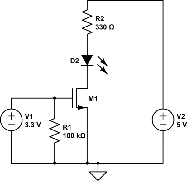
The schema below represent (I think) how it is currently wired, on the left the RPi pin + ground and on the right a 5V DC supply.

schematic

simulate this circuit – Schematic created using CircuitLab

If I remove the MOSFET and plug it directly to the 5V, it light up so this part is ok.

When I set the pin to high, I have 3.3 between it and the ground but nothing shows and from what I understand the MOSFET should be on between 2 and 4V.

I'm not really sure what I've missed but being a bit new to electronics there's probably some beginner mistakes in there.

\$\endgroup\$
2
  • \$\begingroup\$ +1 for a clear problem statement with a good schematic. Actually I didn't read all of your question since the problem was obvious from the schematic and the datasheet, but even that much clear information is all too rare around here. It's nice to find someone asking a question we don't have to tar and feather. \$\endgroup\$ Commented Sep 3, 2013 at 16:29
  • \$\begingroup\$ Thanks, glad you liked it because you can expect more soon :) (beside I'm not too fond of tar nor feathers) \$\endgroup\$
    – hlidotbe
    Commented Sep 3, 2013 at 18:33

2 Answers 2

5
\$\begingroup\$

You have to actually read the datasheet. Note that the gate threshold voltage can be up to 4 V, and that is only where it starts to conduct. This MOSFET is simply inappropriate for this application. It is also much larger and for much higher voltage and power than you need. Those by themselves don't hurt you except that other specs have been traded off to get those. MOSFETs that can handle more than 30 V usually can't be turned on very well by logic level signals, and this one is no exception.

Replace with a more suitable FET, like the IRLML2502, and your circuit should work as shown. Or, you can use a jellybean NPN transistor, like 2N4401, with a base resistor and maybe adjust R2 a bit.

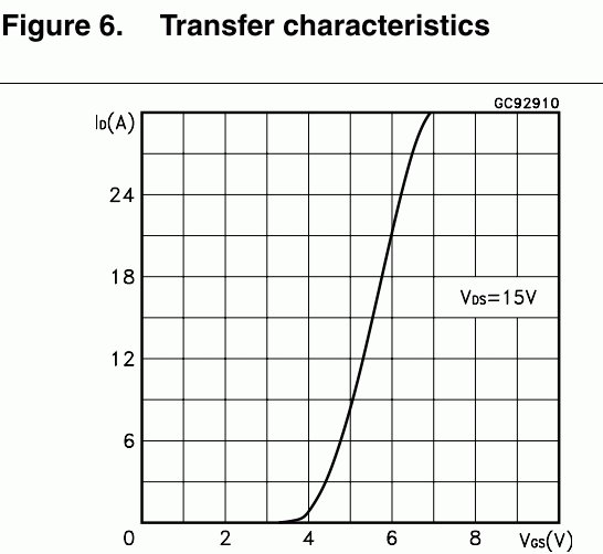
The diagram in the MOSFETs datasheet that could (should?) have alerted you is on p.6:
enter image description here

This diagram shows that your MOSFET can handle no current with its gate at 3V, and it can handle the current it is rated for (16A) from ~ 5.5V. (Note that such diagrams are typical, not worst case, so you can't use them for accurate design calculations, but they still give good indication).

You should use a MOSFET has the vertical part of the curve below 3V. Such a MOSFET will be rated for much lower currents.

If you realy must use a MOSFET like this one you will need to amplify (convert) your Pi's output to a higher voltage, for instance using a MOSFET driver chip.
\$\endgroup\$
3
  • 1
    \$\begingroup\$ The type of MOSFET Olin is referring in this answer is commonly known as "logic-level" - the knee in the Vgs curve is usually at or less than 2.5V. They work great at 5V, and many are quite useable at 3.3V. \$\endgroup\$ Commented Sep 3, 2013 at 17:04
  • \$\begingroup\$ ok that make sense, I'm a total noob in electronics and although I did read the datasheet I clearly didn't understood everything. I thought the threshold was between 2 and 4 and not from 4. I bought them on a hobbyist site and I think they were supposed to be used with an arduino (at 5V I guess it was more suitable). The current setup is at 5V for testing but I'm supposed to drive 12V and a larger amount of current than the IRLML2502 can handle I think but now I know what to look for. Thanks! \$\endgroup\$
    – hlidotbe
    Commented Sep 3, 2013 at 18:39
  • 1
    \$\begingroup\$ @hlid: The gate threshold is between 2 and 4 Volts. But, there are two problems with this. First, you don't know where in there it will be, so it being over 3.3 V is certainly possible. Second, the gate threshold is not the spec you care about anyway. That tells you when the FET starts to turn on, which is not very relevant unless you have to carefully consider off-state leakage. \$\endgroup\$ Commented Sep 3, 2013 at 19:02
0
\$\begingroup\$

If you do have MOSFET that need to be over 4V to closing the gate then you will need to use Isolators - Gate Drivers. I recommend this driver by link below. Never, Never put 15V in series if you buiding half bridge or full bridge. 5V LED in that driver can be in series for full bridge. That requirment you to have two source power supply for single MOSFET. One for Raspberry Pi and other one for 15V gate in MOSFET.

http://www.digikey.com/scripts/DkSearch/dksus.dll?Detail&itemSeq=164920407&uq=635583246599232874&CSRT=6638351088573513399

\$\endgroup\$
1
  • 2
    \$\begingroup\$ That search link seems to be broken for me if you wanted to check it. It might also be worth adding the part number and/or search terms used in case the URL changes in the future. \$\endgroup\$
    – PeterJ
    Commented Feb 1, 2015 at 0:41

Your Answer

By clicking “Post Your Answer”, you agree to our terms of service and acknowledge you have read our privacy policy.

Not the answer you're looking for? Browse other questions tagged or ask your own question.