4
\$\begingroup\$

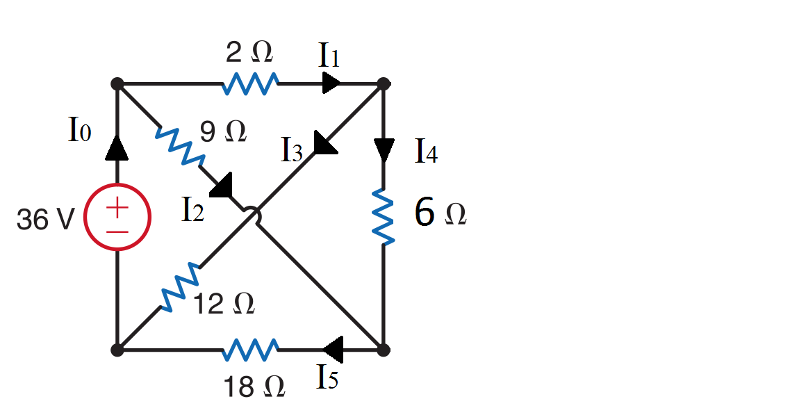
enter image description here

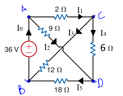
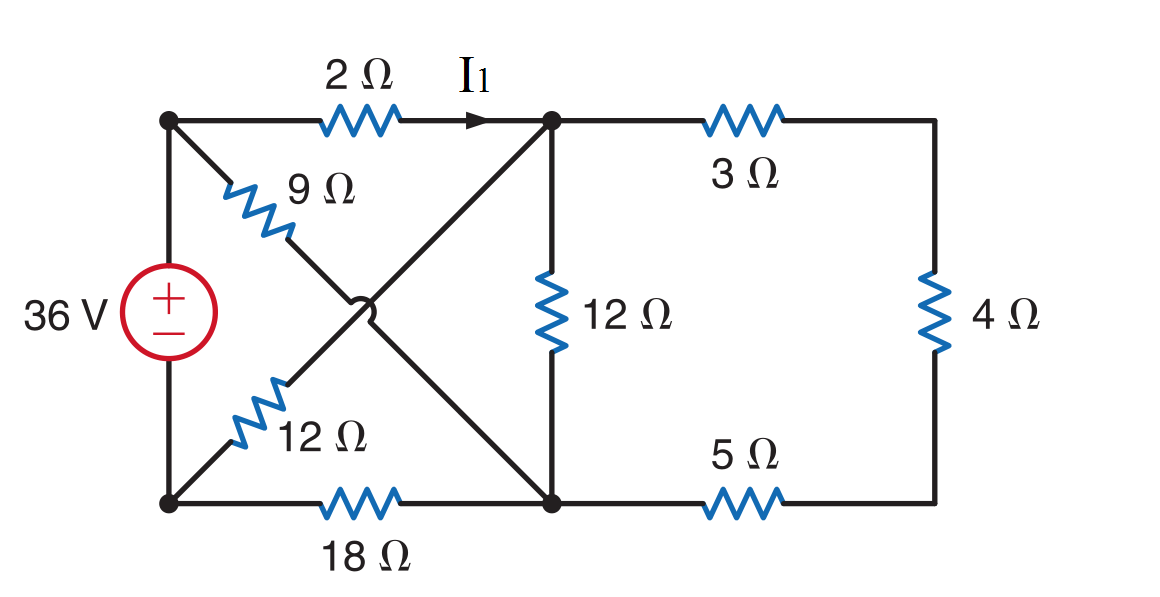
Hello, the original circuit above is where I am trying to find I1, and I simplify it the figure below and assuming the following current directions.

enter image description here

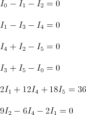
Using Kirchoff current and voltage laws I end up with

enter image description here

However, plugging in the equations into my calculator it says there is no solution. Is it with my kirchoff current equations (first 4 equations) because if I add up all current law equations I end up with 0 = 0. Can anyone tell me what I am doing wrong? Thanks for any help.

EDIT:

As other mentioned I need more KVL equations. But I also need my KVL to be independent loops, so I need at least 3 independent KVL equations.

\$\endgroup\$
5
  • 3
    \$\begingroup\$ Shouldn't "\$12I_4\$" be "\$6I_4\$" in your 5th equation? \$\endgroup\$
    – markrages
    Commented Sep 20, 2013 at 7:57
  • 1
    \$\begingroup\$ Its still not a solvable system of linear equations after that correction. \$\endgroup\$ Commented Sep 20, 2013 at 8:26
  • \$\begingroup\$ I think you need to simplify the circuit and then use a wye-delta transform to make it solvable easily: en.wikipedia.org/wiki/Y-%CE%94_transform \$\endgroup\$
    – Dor
    Commented Sep 20, 2013 at 9:13
  • \$\begingroup\$ There are quite a few more KVL loops available for you to add \$\endgroup\$ Commented Sep 20, 2013 at 10:41
  • \$\begingroup\$ I'd recommend combining 1st and 4th equation, treat the voltage source branch as a supernode \$\endgroup\$
    – Iancovici
    Commented Sep 20, 2013 at 11:11

4 Answers 4

1
\$\begingroup\$

If you use KVL in the other loop (36v i5 and i2) then use that, the other kvl equations and two of the kcl equations it should work.

Adding all the kcl equations should give 0=0. They don't include the voltage so they can't actually solve for anything here.

Using star-delta transforms and mesh analysis can make it a bit easier to solve (transform the delta that doesn't have I1 in it to a star/wye).

\$\endgroup\$
1
  • \$\begingroup\$ Wye-delta (Y-Δ) transform is briefly discussed here \$\endgroup\$
    – jippie
    Commented Sep 20, 2013 at 21:20
4
\$\begingroup\$

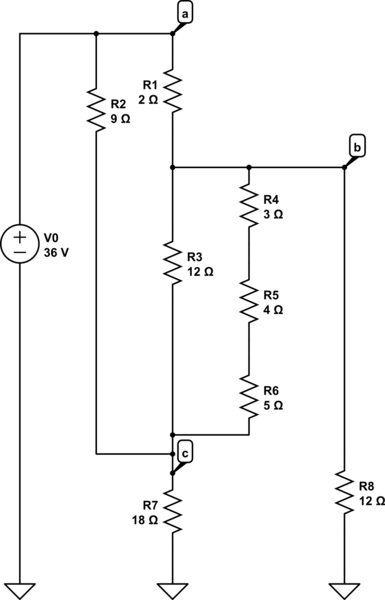
schematic

simulate this circuit – Schematic created using CircuitLab

First, convince yourself that the above re-drawn schematic is the same as your problem original. I may have the numbering off (actually, I certainly do have the numbering off), but it is the approach which is important.

So:

We can make a quick substitution by combining R4 to R6 as R9=12 ohms because they're in series. I probably could also reduce R9 and R3 in parallel, but I'll leave them as-is for now.

Next, write out KCL and Ohm's law (assume currents are flowing "down" through resistors, up through V0):

\begin{equation} I_0 - I_1 - I_2 = 0\\ I_1 - I_3 - I_8 - I_9 = 0\\ I_2 - I_3 - I_7 - I_9 = 0\\ \end{equation} \begin{equation} I_1 = \frac{V_a - V_b}{R_1}\\ I_2 = \frac{V_a - V_c}{R_2}\\ I_3 = \frac{V_b - V_c}{R_3}\\ I_7 = \frac{V_c}{R_7}\\ I_8 = \frac{V_b}{R_8}\\ I_9 = \frac{V_b - V_c}{R_9}\\ V_a = V_0 \end{equation}

Substituting back in:

\begin{equation} I_0 - \frac{V_a - V_b}{R_1} - \frac{V_a - V_c}{R_2} = 0\\ \frac{V_a - V_b}{R_1} - \frac{V_b - V_c}{R_3} - \frac{V_b}{R_8} - \frac{V_b - V_c}{R_9} = 0\\ \frac{V_a - V_c}{R_2} - \frac{V_b - V_c}{R_3} - \frac{V_c}{R_7} - \frac{V_b - V_c}{R_9} = 0\\ V_a = V_0 \end{equation}

A little bit of re-writing (Gn = 1/Rn):

\begin{equation} I_0 + G_1 V_b + G_2 V_c = (G_1 + G_2) V_0\\ (G_1 + G_3 + G_8 + G_9) V_b - (G_3 + G_9) V_c = G_1 V_0\\ (G_3 + G_9) V_b - (G_3 - G_2 - G_7 + G_9) V_c = G_2 V_0 \end{equation}

We have three equations with three unknowns: I0, Vb, and Vc. Once you've solved for these you can calculate I1 easily using R1, Va, and Vb. And yes, this is a solvable system. I'll stop short of just posting the number solution.

Incidentally, this approach is known as Modified Nodal Analysis and is used in SPICE circuit simulation software. It basically adds an extra unknown current for each voltage source, and then adds an extra equation for the difference between the nodal voltages. I simply did some extra "inline plugging in" of the source voltage equation to reduce the set of equations/unknowns to 3. Yes, this approach might look like extra work because you are solving for voltages first, but it is a much more systematic approach, quite robust, and in the long run I find it faster to actually do.
\$\endgroup\$
6
  • 4
    \$\begingroup\$ Wow, +1 for the incredible effort. The circuit was solvable as it was though. You just have to write the right linear equations (the OP had one too many KCL eq and one too few KVL eq), put it in a 6x7 matrix and solve for reduced row-echelon form. \$\endgroup\$ Commented Sep 20, 2013 at 9:47
  • \$\begingroup\$ Yeah, I don't reason well with KVL especially as circuits get more complicated. I can see where the extra KCL equation is, but I have to stare really hard at the problem to find which KVL equation is missing. I'll have my MNA any day. \$\endgroup\$ Commented Sep 20, 2013 at 10:01
  • \$\begingroup\$ It seems valid. My concern was if the OP was doing a homework question that needs to be solved a specific way to count. \$\endgroup\$ Commented Sep 20, 2013 at 10:24
  • \$\begingroup\$ Possibly, the instructions weren't entirely clear because the OP only mentioned Kirchoff's laws, not the actual approach required. MNA uses KCL and ohm's law so as far as I see is just as valid a method as using Mesh Analysis, unless stated otherwise. I've never actually had to solve a problem using KVL and mesh analysis because my professor was opposed to the idea of visualizing current loops and super meshes and I can understand why. \$\endgroup\$ Commented Sep 20, 2013 at 22:43
  • \$\begingroup\$ Thanks for help guys. It's not for homework, but I was just hoping to improve my understanding of the laws. The book solution uses Delta transforms and it becomes rather easy to solve. @trav1s Regarding having too many KCL equations, how do you know you have too many? I just found out for KVL you should only have as many KVL as independent loops there are. \$\endgroup\$
    – roverred
    Commented Sep 21, 2013 at 1:00
1
\$\begingroup\$

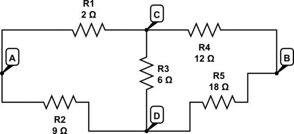
Here is an easy way

enter image description here

schematic

simulate this circuit – Schematic created using CircuitLab

This is an unbalanced Wheatstone bridge

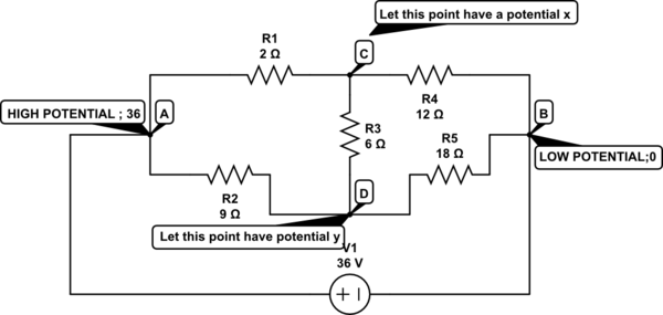
Here is a clever way to find Current in each Branch

schematic

simulate this circuit

Now I am going to Write A KCL equation for node C and D

I will use the potentials marked in the schematic

So for C

Sum of current converging on a point = 0

$$\frac { X-36 }{ 2 } \quad +\quad \frac { X-0 }{ 12 } \quad +\quad \frac { X-Y }{ 6\quad } \quad =\quad 0$$

Likewise for D

$$\frac { Y-36 }{ 9 } \quad +\quad \frac { Y-0 }{ 18 } \quad +\quad \frac { Y-X }{ 6\quad } \quad =\quad 0$$

Solve these 2 equations

You get

X = 30

Y = 27

Now we can get our answers

$${ I }_{ 1 }\quad =\quad \frac { { V }_{ A }\quad -{ V }_{ C } }{ R } \quad =\quad \frac { 36-X }{ 2 } =\frac { 36-X }{ 2 } =\quad 6(0.5)\quad =\quad 3\quad A$$

So you now can find every current

\$\endgroup\$
2
  • \$\begingroup\$ There is an embedded schematic drawing option in the site instead of MS Paint. Also could you please explain your answer in a little bit more detail. \$\endgroup\$ Commented May 26, 2016 at 6:20
  • \$\begingroup\$ There a detailed explanation \$\endgroup\$
    – sidt36
    Commented May 26, 2016 at 7:33
0
\$\begingroup\$

Here is an alternative for solving the circuit.

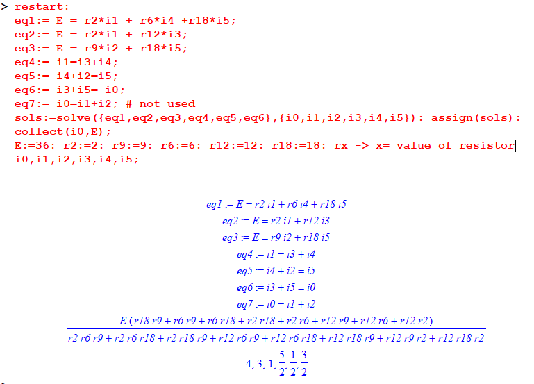
Made with Maple sheet. Used 2nd picture of OP question. Use eq6 OR eq7.

enter image description here

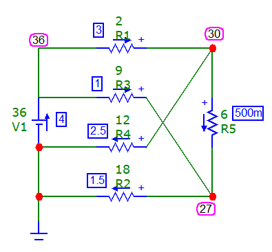
Made with microcap v12

enter image description here

\$\endgroup\$

Your Answer

By clicking “Post Your Answer”, you agree to our terms of service and acknowledge you have read our privacy policy.

Not the answer you're looking for? Browse other questions tagged or ask your own question.