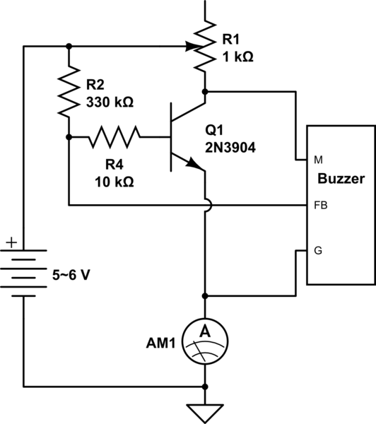
I am using a EAST EFM-290ED Buzzer Alarm. It needs to be oscillated to work.
I found a simple one transistor setup that makes it work, but I am not sure if it is working well for this buzzer.
Update: I found that this type of oscillator is called a Hartley oscillator?

simulate this circuit – Schematic created using CircuitLab
When the pot is below 25Ω, the buzzer is off and 3mA. When its ~30Ω the buzzer is on, and I get about 3.1mA. The buzzer and current peaks around 500Ω, 3.45mA. And at the high end, 1k, I get 2.9mA and a softer buzzer than the 500Ω point.
But its not nearly enough compared to what it should be (4.5v (3xAA) but pretty ear piercingly loud at close quarters, it was used in a Carbon Monoxide alarm).
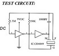
Seems the buzzer needs a 3.4khz oscillation. I am not sure if the FB pin provides that oscillation, or if the transistor can keep up.
Does anyone have a little insight into this? Should I change the pullup r2 or the base resistor r4? Is a 2n3904 suited for this? (The original diagram suggested 20k for R4, I tried 10k and 33k. I also tried 33k for R2).
Secondly if I wanted to control this through a microcontroller, could I use a second npn transistor, where the Ammeter is?
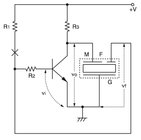
Update: This Murata procedure note (Page 5 Self Drive Method) for the same type of piezo with feedback shows:

While stating:
- Phase difference between νo and νf shown in Fig. 9 must be 180 degrees.
- The following conditions must be satisfied: νf / νo >= (R2+hie)/(hfe · R3) where hie: Input impedance of transistor and hfe: Current amplification
- Set R1 so that the D.C. bias point of transistor, VCE is half of supply voltage.
- Adjust R2 so that spurious oscillation is not applied to oscillating waves.
Hie for the 2n3904 is 1k min to 10k max. hfe at Ic 1mA is 100 to 300. I am not sure if my existing values meet these conditions, (unsure of how to calculate R1 so VCE is half of V, or how to figure Vo and Vf)

