5
\$\begingroup\$

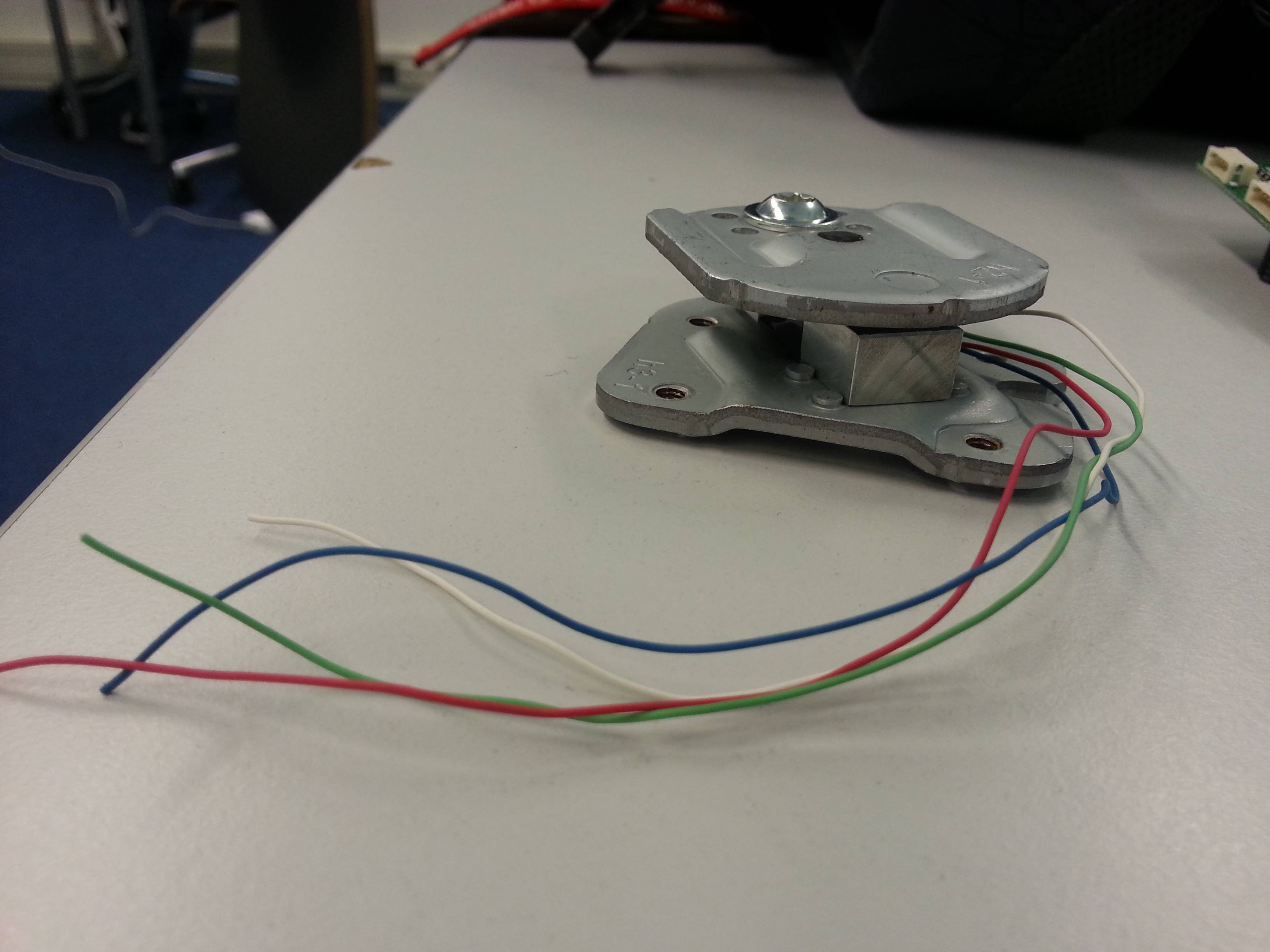
We have a Wii balance board pressure sensor and were wondering how we could connect this sensor to an Arduino board.

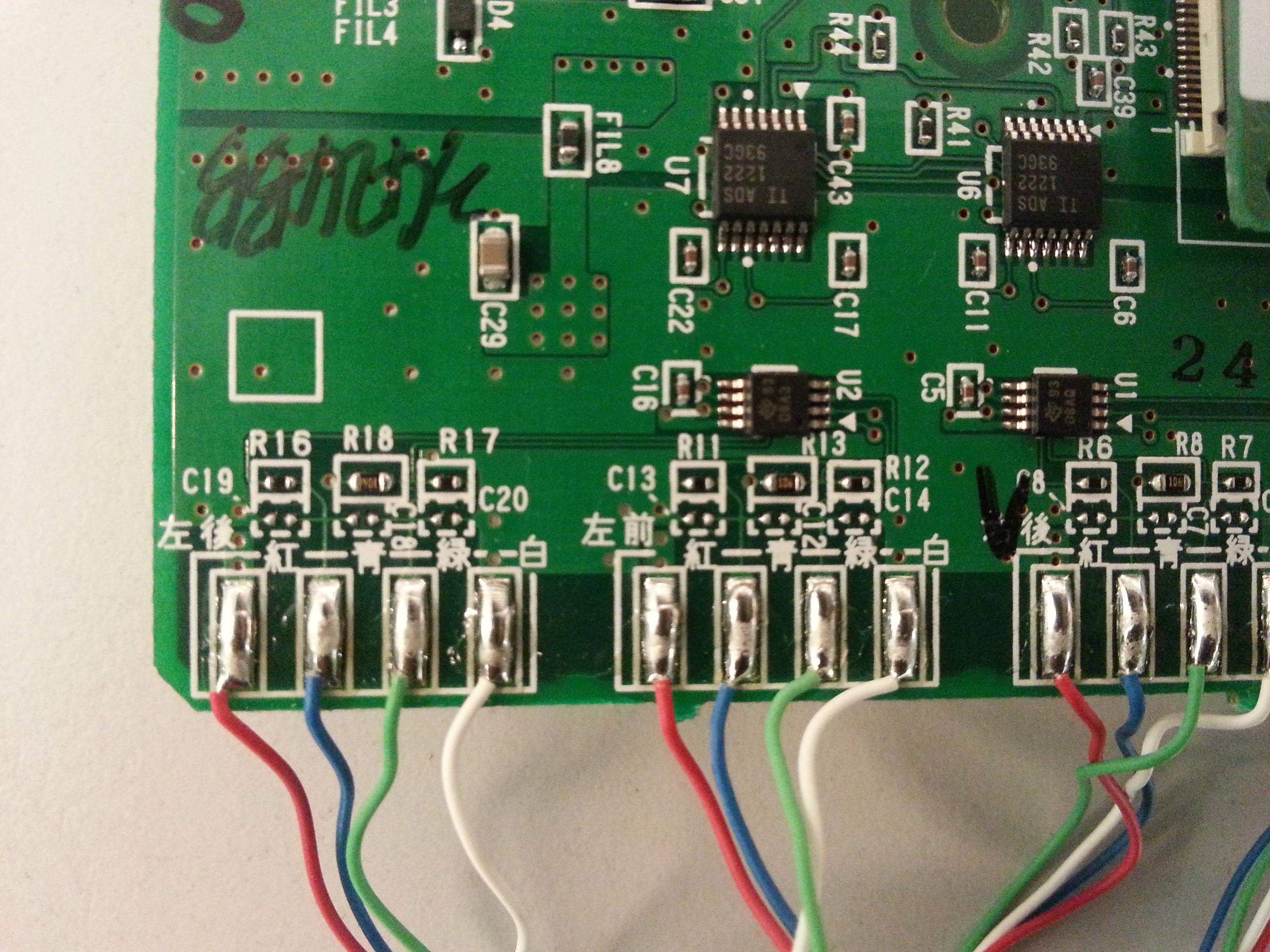
On the circuit board (see picture) of the Wii Balance Board are Japanese characters printed, only those are pointing out which color there must be. The problem is, most pressure sensor examples of the Arduino are with 2 cables, but the Wii pressure sensor got 4 cables. So which cable is for what?

enter image description here

enter image description here

enter image description here

\$\endgroup\$
7
  • \$\begingroup\$ I think a Wii balance board has four sensors- one in each corner of the board. I think the board is battery powered and communicates via Bluetooth. en.wikipedia.org/wiki/Wii_Balance_Board I'm not sure you have what you need there. \$\endgroup\$
    – mikeY
    Commented Sep 30, 2013 at 15:41
  • 1
    \$\begingroup\$ Hi Mikey, thanks for you answer. Yes we already now that it has 4 sensors, but they have 4 cables attached to their part. Problem is we have no clue which role the red/blue/white/green cables got and how we can connect this sensor to an arduino board. \$\endgroup\$ Commented Sep 30, 2013 at 16:30
  • \$\begingroup\$ If the thing in the third picture is one of the sensors, it probably has power, ground, and two communication lines. See if this is helpful: freepatentsonline.com/20090093305.pdf Especially 0100 and 0108 on page 7. \$\endgroup\$
    – mikeY
    Commented Sep 30, 2013 at 19:17
  • 1
    \$\begingroup\$ For anyone coming to this question "MLC714N load cell" is the strain gauge name to google \$\endgroup\$
    – Blundell
    Commented Sep 12, 2017 at 20:34
  • 1
    \$\begingroup\$ Yeah I had to read around, but I get it now, these are the 4 wires out of the wheatstone, not 4 wires you would attempt to input into a wheatstone \$\endgroup\$
    – Blundell
    Commented Sep 13, 2017 at 19:23

2 Answers 2

5
\$\begingroup\$

It has two TI ADS1222 2 channel Serial ADC converters, for four sensors total.

The two smaller ics labeled TI 93 DBA3/DBAQ are probably opamps (can't find the part) but they should trace out to the ADC converters. Most likely, LMV932s, dual low voltage high quality opamps, but they don't match the suggested topcodes.

The four pin connections are Strain gauge wheatstone bridge connections.

The topmost (White) connection for each of the four bridge connections is the ground; relative to this, the two middle connections should be at 1.2 VDC, and the bottom should be at 2.7 VDC

The entire board acts like a standard wii remote, with a standard i2c wii balance board extension/accessory. It can be accessed via Bluetooth, or you could maybe tap into the i2c lines as well.

See http://wiibrew.org/wiki/Wii_Balance_Board for the bluetooth/hid descriptions and information.

Frankly, the bluetooth way is the easiest. Unfortunately, it's not as easy as the Wii Nunchuck being a simple i2c device with a connector.

\$\endgroup\$
2
  • \$\begingroup\$ Note that connecting via Bluetooth requires a L2CAP module. \$\endgroup\$
    – emc
    Commented Apr 6, 2015 at 0:55
  • \$\begingroup\$ My board has the smaller IC's labelled as TI 81 ODBQ Looks like these are ti / Burr Brown OP2333 CMOS Op Amps. \$\endgroup\$ Commented Sep 28, 2019 at 20:59
0
\$\begingroup\$

I know this is a very old topic, but it looks like there is no other resource on the internet. As Peter said, it looks like the smaller IC is a OP2333. I've soldered on the OUT A and OUT B pins of this IC wires, which I connected to the analog inputs from the arduino (A0-A3). I also took a 3.3V from the board and connected it to the reference pin for the ADC of the arduino. This will work and you get usable values.

\$\endgroup\$

Not the answer you're looking for? Browse other questions tagged or ask your own question.