4
\$\begingroup\$

I'm designing my first PCB but I'm a bit stuck on how I'm going to use it.

At the moment my design is on breadboard with a single input and output.

I want to use my PCB as like a little module where I can just put a input wire into it. Also how I would connect up power and found etc.

I thought of using a row of female jumper connectors just like the black strips on an arduino and then I can just insert the wire inputs into the headers. However it seems like its not such a standard component and farnell and rs don't stock the jumper.

So it got me thinking what is the commonly used connector or method just for simple input and output.

\$\endgroup\$
4
  • 1
    \$\begingroup\$ You might like to search for "2.54mm receptacle" on Farnell. Plenty of options, e.g. part number #2308804. These are very standard components. \$\endgroup\$
    – David
    Commented Oct 17, 2013 at 21:11
  • \$\begingroup\$ For one wire to plug and remove for repeated use, maybe a pin-terminated jumper wire is better. But it might be better to use a row of header pins with a compatible socket so your modular PCB can communicate and be powered by a more primary board. This is probably more dependent on your design. \$\endgroup\$
    – Shabab
    Commented Oct 17, 2013 at 21:14
  • \$\begingroup\$ Thanks David, didn't try using the word receptical. But wow I found one but why are they so expensive? SKU 1667472 \$\endgroup\$ Commented Oct 17, 2013 at 21:25
  • \$\begingroup\$ Yep Shabab, pin-terminated jumper wire is what I want preferably but its the name of the femnal connector / header that's giving me trouble . I don't know what to look for, and what I have found are expensive! £1+ \$\endgroup\$ Commented Oct 17, 2013 at 21:28

2 Answers 2

5
\$\begingroup\$

Option 1:

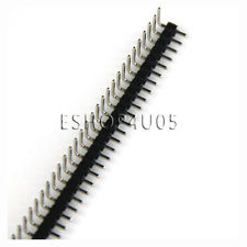
  • Solder a 0.1" (2.54 mm) male pin header on the PCB with as many pins as needed, and the cheapest female 0.1" connector you can find to connect to it.
    Pin headers can be had for as little as US$0.96 including international shipping, for 80 pins, on eBay. Simply cut and use as many pins as you need:
    Pin header

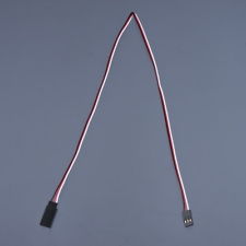
    "Servo cables" for RC aircraft have 3 connections, and are pretty inexpensive as well, again this one is US$0.96 including international shipping on eBay:
    Servo Connector
    That gives you 3 wires, for power, ground and your signal, just perfect.
    To address the question about how the connectors will stay connected to the PCB: The female connectors have a spring-loaded action inside, to grip the male pins. However, a firm tug will pull the connector off.

Option 2:

  • Use industry-standard JST (Japan Solderless Terminal) connector pairs, with the male side soldered to your PCB.
    This one, for instance, is US$1.86 for 5 sets of 4 connectors each:
    JST
    These have a snap-fit action in the plastic housing, hence a more robust connection than the plain pin headers.
    This seems to be the most cost-effective option, if you can find some use for the other 4 connector pairs.

Option 3:

  • Use one of a variety of common connectors you can either liberate from old equipment or buy dirt cheap from a local audio or electronics repair store, such as used for battery connectors or headphones, e.g.
    • 2.1 mm barrel jack on the wire side and its socket on the PCB side, if 2 conductors will suffice, i.e. signal and ground
    • 3-pin (TRS) or 4-pin (TRRS) headphone socket on the PCB and corresponding pin on the wire side, if 3 or 4 conductors will suffice.

Option 4:

  • Any number of increasingly esoteric and increasingly expensive board to wire connector pairs, depending on desired number of connection cycles, and other constraints such as current capacity and size. Electronic component vendors like DigiKey provide a surfeit of options.
\$\endgroup\$
2
  • \$\begingroup\$ Note: assembling your own tiny JST terminals involves either a very expensive crimp tool or manipulating tiny objects with pliers. \$\endgroup\$
    – pjc50
    Commented Oct 18, 2013 at 10:59
  • 1
    \$\begingroup\$ @pjc50 Hence the link I provided: It comes with wired pre-crimped, as the photo shows. \$\endgroup\$ Commented Oct 18, 2013 at 11:09
1
\$\begingroup\$

For permanent connections, I've often just soldered wires into pads - you may have to make a single pin component (module/footprint) for this, depending on your CAD system.

For less permanent connections, there are several styles of PC-mounted screw or spring terminal blocks that will take single wires.

Unless you have suitable tooling to make the mating cables, I would avoid the .025" post headers, but there are other connectors that can be mounted directly to a PC board.

\$\endgroup\$
2
  • \$\begingroup\$ Ah intresting. So something like this SKU on farnel: 2072367? I see some other types £1+ that look the same but with an orange lever, I assume you press it down to hold the wire in, but this cheaper one with no orange leaver..I cant seem to figure out how you would get the wire to stay. But thanks for the name also. Its cheaper but not as cheap as I hoped. \$\endgroup\$ Commented Oct 17, 2013 at 22:07
  • \$\begingroup\$ @binarysmacker - Yes - that Farnell part is the sort of thing I was thinking of. With the spring types, you usually press the button to insert or remove the wire - with the button or lever released, the internal spring holds the wire. There are similar things with screw clamps. \$\endgroup\$ Commented Oct 17, 2013 at 22:14

Your Answer

By clicking “Post Your Answer”, you agree to our terms of service and acknowledge you have read our privacy policy.

Not the answer you're looking for? Browse other questions tagged or ask your own question.