3
\$\begingroup\$

Why some of JFET preamp's for guitars don't bias the gate to Vgs(off)/2 and just reference it to ground? (Setting Zi)

This also lead to just direct coupling the guitar output to the gate.

As far as I understand with N-JFET's one should apply a negative voltage up to Vgs(off) to control the current the channel. And that on the ohmic region near to Vgs=0 the transfer curve becomes more non-linear.

The direct coupling non-biased design would mean the preamp or voltage buffer would be working on the Vgs=0 non-linear zone and that on the positive semi-cycle of the input sine wave the gate will be forward biased and would not make the channel less resistive (since Ids is already max and the channel saturated) then the output would be quite different from the original.

One example of these designs:

Ruby: MPF102 input buffer for a LM386

Explanations like this one has a DC bias on the gate (that doesn't matters on the AC analysis though).

As far I have figured out if we put our reference on the Source, Rs is biasing both Source and Gate, making the Source more positive than the gate, and the Gate as negative as Vs.

But then on the Ruby circuit, taking the Source as reference, the Gate would be at -9V above the -8V needed to reach cut-off voltage on a MPF102 and -6V with a 2N5457. A positive semicycle above 1V should make a difference but a negative semicycle won't.

My approach is wrong? I know that DC and AC analysis should be done way different from this, but I don't understand the physics mechanics that are working here.

EDIT:

Setting aside that learn how things work is a good thing, I wanted to understand this to replace that MPF102 with an 2N2302 with smaller specs than the MPF102: Idss=5mA; Vto=-4V. (MPF102 and 2N5457 are not available here) I was worried if I would have to change values to achieve a proper polarization since my signal in a worst case scenario goes as high as 2Vpp and the MPF102 Vto is -8V. I understood that it was a voltage follower but failed to understand the inner workings so these questions came up.

\$\endgroup\$
1
  • \$\begingroup\$ I have choosen Andy-aka reply as the answer due to the simplicity of his response but mostly because it's more oriented to the context of my questions. Though, I would like to state that my doubts got cleared by @Alfred-centauri equations and Andy-aka's practical case. \$\endgroup\$
    – Sdlion
    Commented Oct 22, 2013 at 23:04

4 Answers 4

2
\$\begingroup\$

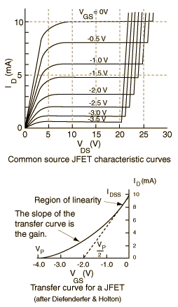
Maybe this will help: -

enter image description here

For no particular JFET, the characteristic might be something like the above. Importantly, and ignoring when \$V_{DS}\$ is 5V or less, the gate bias voltage sets the operating current for the drain.

So, for JFETs with a simple gate bias connected to 0V, more drain current means more source current which means more source voltage which means a bigger negative bias on the gate relative to the source and this means "regulation" i.e. it finds its own level - there is negative feedback and very elegant it is too. This keeps it in the linear region.

For a guitar amplifier where the input signal is a few hundred millivolt p-p at maximum, the drain current is modulated by the gate ac voltage quite linearly.

If the supply is 10V (easy to see on the curve) and the gate voltage is 3V below the source, the drain/source current will be about 1.4mA and this is self-sustained (regulated) when the source resistance is about 2k2.

Picture stolen from here (a very good website for plenty of stuff).

\$\endgroup\$
3
  • \$\begingroup\$ From @Alfred-centari 's equation the bias voltage would be determined form the Rs and JFET's Beta. But from your explanation as long the Rs sits between a reasonable range the regulation would sit on the linear region by itself. Then the Rs should be selected just taking in mind the desirable Zo as long is not lower or near the small internal Rds? I'm trying to minimize the worries of changing the JFET specified for the Ruby circuit. \$\endgroup\$
    – Sdlion
    Commented Oct 22, 2013 at 18:44
  • \$\begingroup\$ If you change the jfet you are likely to have to tweak the value of the source resistor due to variations in the gate voltage thresholds. There are more elaborate ways of biasing a jfet which guarantee better reproducability of course but this is the simplest circuit and pretty much resembles the biasing arrangement on a triode valve hence it's popularity with guitarists. Me, I prefer VSTs LOL. \$\endgroup\$
    – Andy aka
    Commented Oct 22, 2013 at 18:50
  • \$\begingroup\$ I have developed a fair reservation against the tale of the "linearity" of the JFET over the years. For small signals, true, it can be accepted to be linear, but so can any transfer function. Weak 20th cent. magnets made this acceptable I guess. But modern humbuckers can burp out 100s of mV - not just during attack. And if you use an appreciable share of the total Vgs range, it will be audibly nonlinear. That is why I eventually overhauled my J201 based FET cable (less than -1V Vgs,off) with a J111 (-7V Vgs,off) and outputted into a current mirror to fit everything into the 12V DC supply. \$\endgroup\$
    – tobalt
    Commented Apr 14, 2023 at 7:24
4
\$\begingroup\$

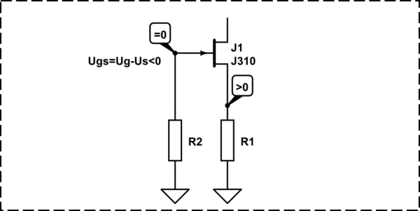
There is bias on the gate and this bias is as expected negative:

As long as the bias is the voltage from the gate to the source:

$$ U_{gs} = U_g - U_s = 0 - positive < 0 $$

schematic

simulate this circuit – Schematic created using CircuitLab

BTW, JFETs can work with 0 bias when the input signals are in mV range. Such small signals can't open the PN junction of the gate, so the gate current is still close to 0, but the slope of the JFET is maximal.

\$\endgroup\$
4
  • \$\begingroup\$ But a positive semi-cycle of an AC signal (N-JFET) would still be ignored and result in a distorted output? \$\endgroup\$
    – Sdlion
    Commented Oct 22, 2013 at 18:30
  • 2
    \$\begingroup\$ @Sdlion - Not at all. The positive semi-cicle of the AC signal will still be lower that the Vs and Vgs will remain negative - less negative of course, but still negative. \$\endgroup\$
    – johnfound
    Commented Oct 22, 2013 at 18:34
  • \$\begingroup\$ Oh yes, I forgot that on a common drain setup. Well I mean in the case you mention, when is working with a 0V bias \$\endgroup\$
    – Sdlion
    Commented Oct 22, 2013 at 18:46
  • 1
    \$\begingroup\$ @Sdlion - Don't forget that the NP junction opens on 0.5..0.6V forward, positive voltage. So, if the positive semi-cicle of the signal have amplitude less than this value, the gate junction will stay closed and there will be no gate current nor distortions. \$\endgroup\$
    – johnfound
    Commented Oct 22, 2013 at 18:57
1
\$\begingroup\$

The JFET, like a vacuum tube triode, is normally "on". By placing a resistor in series with the source, the JFET "self-biases".

Since \$V_G = 0 \$ and \$V_S > 0 \$ for non-zero drain current, \$V_{GS} = V_G - V_S \$ is negative.

In words, think of it this way: the current through \$R_S\$ will be whatever it needs to be such the \$V_{GS}\$ is consistent with that current.

If \$I_D\$ were zero, \$V_{GS}\$ would be zero but this is inconsistent since, for zero bias, \$I_D = I_{DSS}\$.

If, \$I_D = I_{DSS}\$ then \$V_{GS}\$ would be negative but this is also inconsistent since, for negative bias, \$I_D < I_{DSS}\$.

Thus, we conclude that \$0 \lt I_D \lt I_{DSS} \$; the JFET has biased itself on.

In equations, we have, for the JFET:

\$I_D = I_S = \beta (V_{GS} - V_{TO})^2 \$

And, for this circuit:

\$V_{GS} = -I_S R_S = -I_D R_S\$

Thus:

\$I_D = \beta (-I_DR_S - V_{TO})^2 = \beta (I^2_DR^2_S + V^2_{TO} + 2I_DR_SV_{TO})\$

This is a quadratic equation in \$I_D \$ that can be solved for DC drain current.

\$\endgroup\$
2
  • \$\begingroup\$ So a capacitor coupling would be only necessary if the signal carries a DC component that could shift the self-biased gate? Though a passive guitar pick-up usually doesn't hold any DC component, and active one it would. So I guess it would be better to include one. I think you're not mention it but this self-biasing would sit on approximately Vto/2 ? This worries me since my ratio Vin-pp/Vto is not as good I would like \$\endgroup\$
    – Sdlion
    Commented Oct 22, 2013 at 18:06
  • \$\begingroup\$ Let me sit and solve the equation for my case. I think I don't needed to ask what I wrote before if I know already Id and have the Vgs equation too. The values of Id would also help me to keep the polarization on my Idss range \$\endgroup\$
    – Sdlion
    Commented Oct 22, 2013 at 18:15
1
\$\begingroup\$

The linked circuit shows an example of JFET "self-bias", which is a popular biasing method in general. It is not something particular to guitar preamps.

A N-JFET channel normally conducts, unless the gate is brought sufficiently lower compared to the source to achieve "pinch-off". In other words, it is a "depletion mode" device. So, the current flowing through the JFET generates a voltage on the source resistor, which lifts the voltage at the source terminal at the ground. The grounded gate is then somewhat negative with respect to the source, so the bias is somewhere between "full on" and "pinch off".

(A bias closer to pinch off results in less quiescent current through the channel, prolonging battery life, at the cost of less gain.)

You might be confusing JFETs and MOSFETs. The circuit configuration would not be appropriate for MOSFETS. That is, not for the more common enhancement mode MOSFETs, which are off unless there is a sufficient gate voltage above the source (or below, for P-channel). The self-bias circuit used for JFETS (which are depletion mode devices) is in fact appropriate for depletion-mode MOSFETS, which can be used in place of JFETs.

\$\endgroup\$
1
  • \$\begingroup\$ What interest me the most in this specific case is where this self-bias would set to avoid distortion of my signal. From Alfred's equation I could infer that this bias would depend entirely on each JFET's beta, and that'd the reason why the answer "the bias is somewhere between" is common, and calculate it would be a waste. Your practical advice on the effects of the position of the bias on the quiescent current and battery life is quite appreciated! Thanks \$\endgroup\$
    – Sdlion
    Commented Oct 22, 2013 at 18:21

Your Answer

By clicking “Post Your Answer”, you agree to our terms of service and acknowledge you have read our privacy policy.

Not the answer you're looking for? Browse other questions tagged or ask your own question.