0
\$\begingroup\$

I'm aware that there have been many questions about this series of relays, but I've read them and still can't get this working.

I have this version, with 4 relays.

I'm currently wiring:

  • 5v Arduino -> VCC
  • GND Arduino -> GND
  • I/O 13 Arduino -> IN1

I have bridged VCC and JD-VCC.

I'm running the Arduino blink example sketch, but nothing happens. I've checked it's using the right pin, I've checked that the code is running correctly, but I still can't get it working.

No noise is heard when the IN1 switches from high to low or visa versa, and the status LED doesn't come on either.

I've also tried switching out Arduinos, in case it was an issue there, but no luck.

Can anyone help?

\$\endgroup\$
12
  • \$\begingroup\$ What does the print on the relay itself say? What's before the VDC? Do you have a multimeter to check the voltages on the module? \$\endgroup\$
    – jippie
    Commented Nov 7, 2013 at 17:36
  • \$\begingroup\$ It's 05VDC-SL-C \$\endgroup\$
    – Alfo
    Commented Nov 7, 2013 at 17:38
  • \$\begingroup\$ And I'm afraid I don't have a multimeter. \$\endgroup\$
    – Alfo
    Commented Nov 7, 2013 at 17:39
  • \$\begingroup\$ Does the LED on Arduino blink? Does the LED on the relay module blink? \$\endgroup\$
    – jippie
    Commented Nov 7, 2013 at 17:42
  • 4
    \$\begingroup\$ You should really consider buying a multimeter, they come extremely cheap up to extremely expensive and basically you get what you pay for. If you are unsure if you want to spend much and just want to use it for small signal stuff, buy one for €10 at the local hardware shop. If you want a decent one you'll have to spend somewhere around €100, those are safer and more accurate. \$\endgroup\$
    – jippie
    Commented Nov 7, 2013 at 17:53

4 Answers 4

3
\$\begingroup\$

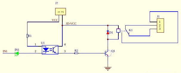
There are a few failure points. image

The first is the Opto side of the Optocoupler. R1, The Opto Led, and the IN1.

The second is the transistor side of the optocoupler. The Opto Transistor, R2, and Q1.

The third one is the Relay and Flyback Diode With Q1 as well.

The final one is the headers and the traces, especially since you have desoldered and resoldered new headers to the board.

The easiest thing to do is test each part. Using two wires, from a 3x AA (4.5v) battery pack, or a 5v supply, connect power and ground directly to the relay's coil pins, bypassing everything else. If it clicks, it works. If it doesn't, the relay is bad OR there is a short.

Then try power to the JD-VCC point & R2 away from Q1. If it works, the Q1 transistor is good.

Finally, apply power to the far side of R1, and ground at the cathode of the IN1 led on the board. If the led lights, then the opto side of the coupler and the IN1 work.

If they all work, then it is an issue with your soldering job. If they don't work, then it could still be an issue from your soldering job, and a multimeter with continuity test would be needed.

\$\endgroup\$
3
\$\begingroup\$

I bought a couple of dual relay modules recently and was having the same issue. The problem might be you bought an "Active low" relay module. What that means is that the "in" is not wanting a high signal from the GPIO. Instead it is looking for a ground. If you wire you vcc to 3.3 or 5 volts, you ground to a ground, then try taking a small piece of wire and jumping the ground to the in pin. Your relay will probably trigger.

So what is the fix?

In1 and ground get wired to ground. VCC goes to your GPIO pin. JD-VCC goes to your plus 3 or 5 volts. (I found 3.3 works, but not a satisfying hard like 5v!)

I know I am answering a very old question, but excited to share a solution.

\$\endgroup\$
2
  • \$\begingroup\$ This is a bit weird. It sounds a bit as if you think that a "low" from the arduino is different from ground. Since he tried with the blink sketch it will toggle the GPIO both high and low, so it doesn't matter if it's active high or active low. It should still toggle. \$\endgroup\$
    – pipe
    Commented Dec 7, 2017 at 18:21
  • \$\begingroup\$ You shouldn't power the VCC pin of a relay module from an MCU GPIO. It might work with one or two relays with your particular loads, but the GPIO won't be happy about supplying the VCC for relays. The correct approach with active low is actually just inverting the logic on your output. \$\endgroup\$
    – Wesley Lee
    Commented Dec 7, 2017 at 19:19
0
\$\begingroup\$

1) Run the relay board direct off 5v and not off the Arduino.

2) Try IN2, IN3 and or IN4.

3) Try a hard wired 5v and ground into the relay board, with the IN signal actuated by a physical momentary switch, taking the Arduino out of the equation

If the board still doesn't work you may have torn it up with your soldering job.

\$\endgroup\$
0
\$\begingroup\$

Read the top of the relay module

SRD-12VDC-SL-C indicates that it require 12v to operate SRD-5VDC-SL-C indicates that it require 5v to operate SRD-3VDC-SL-C indicates that it require 3v to operate

You can use appropriate voltage to trigger the relay coil don't worry about the circuit. Just use two wires connected to 3v/5v/12v and touch the wires on the coil terminals of the relay if the relay is not bad then you will listen tiktok sound :)

\$\endgroup\$

Not the answer you're looking for? Browse other questions tagged or ask your own question.