I've been having some problems with memory ICs, specifically Flash and EEPROM.
I've had some experience with the 7400 series for some time...logic gates are pretty straightforward. Input something, output something. But as soon as I move on to something more complicated, things just don't work for some reason. Everything looks okay on paper, but when I build it, it does not work. So how do you know that everything inside the chip is working the way they should?
The particular issue that I am facing is trying to program a 28C64 EEPROM IC. Reading it returns all ones, as expected. But as for trying to program, no dice.
I don't have time to create a schematic right now, but I might be able to add it later. For now, please try to visualize... :)
OE_is held high.WE_andCE_is manually controlled via switchesD0toD7is connected to DIP switchA0toA11are connected to a 12-stage binary counter, a 74HC4040 ICD12is manually controlled via a DIP switchTwo buttons are used to control the binary counter, one to increment and one to reset
I've checked the inputs, and they are all correct. For the sake of simplicity, I tried to program pattern 0x55 (or 01010101) to address location 0x0000.
The procedure that I am using is as follows:
- Connect
GNDandVcc - Set DIP switch for data to
01010101 - Reset the binary counter (so that it outputs
000000000000) - Set the
D12switch to0 - Set
CE_to0 - Set
WE_to0 - Set
WE_to1 - Set
CE_to1 - Remove power
Why would this not work? I built another circuit on a breadboard to read it but it shows 11111111.
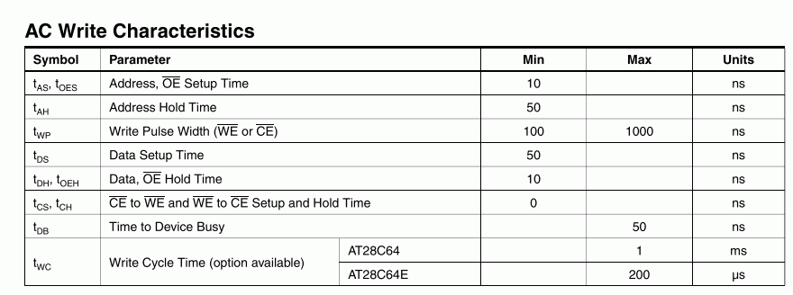
I am toggling the WE_ by hand, but it's usually supposed to be controlled by a CPU or a microcontroller. Is there a maximum time limit for the write pulse?
Also is it safe to disconnect Vcc power right after I program it? (Probably a stupid question)
Thanks, fuzzyhair2
P.S. Same thing happens for the flash memory, the 29F010. After the unlock cycle and program, I see all ones.

