10
\$\begingroup\$

A typical distribution grid supplies 6 or 10 kilovolts AC to a substation near the consumers. This is typically done with a three-phase line without neutral - just three wires going in parallel. Then there's a transformer that lowers the voltage to something like 110 or 230 volts AC.

The consumers typically have single-phase load and so here comes the neutral - we now have three phase wires and the neutral wire as the transformer output and those single-phase loads from different consumers are connected to phases in round-robin fashion so that the current in the neutral is hopefully minimized and phases conduct equal currents. Yet unless the load is perfectly balanced different phases will conduct different currents on the secondary side of the transformer and the difference is the current flowing through the neutral.

How is that addressed on the primary side and the high voltage line where there're just three phase wires and no neutral wire?

\$\endgroup\$
1
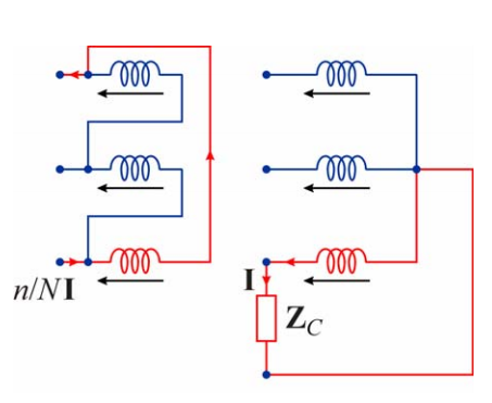
  • \$\begingroup\$ Short answer: due to amp-turns balance, single-phase loads on the wye LV of a delta-wye transformer appear as phase-phase loads on the delta HV. So no neutral current flows in the HV due to single phase LV loads. Note: The HV system (delta-connected, no neutral) is earthed via a "zig-zag earthing transformer", which is a way of getting a earth connection on a delta-connected system that doesn't usually have a earth conductor. They're called "neutral earthing compensators" in other parts of the world. I'll write up an answer as time permits. \$\endgroup\$ Commented Dec 17, 2013 at 11:47

3 Answers 3

15
\$\begingroup\$

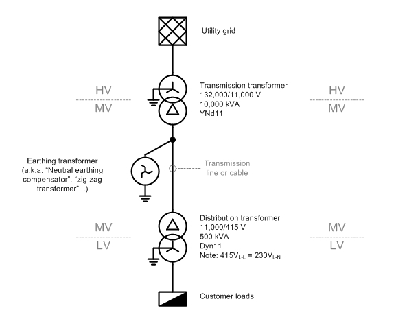
A typical distribution network in Australia will look something like the below.
enter image description here

The "MV" section is a delta-connected "three-wire" system, so you are correct in asserting that there is no neutral wire. However, there is a path for neutral or "zero-sequence" currents to flow to ground, via the earthing 'zig-zag' transformer that is installed for this purpose. (The reasons for installing a earthing transformer deserve a separate question and answer.)

There are a few phenomena that may give rise to neutral current on a MV transmission line, but unbalanced LV loads, which cause a current to flow in the LV star-point/neutral, don't cause MV neutral current.

Why is that?
enter image description here

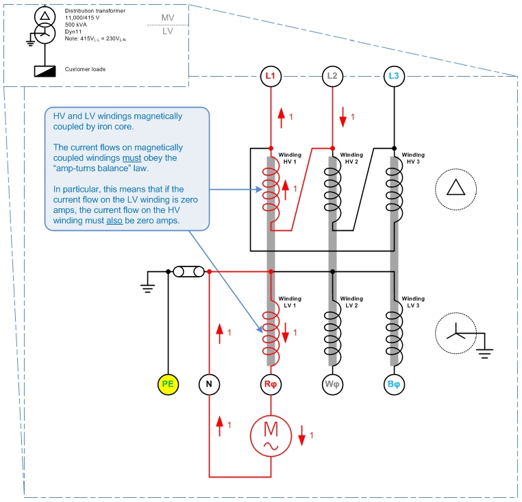
The picture above shows a delta HV, grounded-star LV system. There is a single-phase load which draws 1 unit (1 p.u.) of current from LV winding 1, with the current returning via the LV neutral.

What happens on the HV?

Each of the transformer's HV and LV windings are magnetically coupled by iron cores, so that the law of "amp-turns balance" must apply. I.e. conservation of energy applies between the pairs of HV and LV windings, HV1-LV1, HV2-LV2, and HV3-LV3.

That means that a 1 p.u. current on winding LV 1 must be balanced out by a 1 p.u. current on winding HV1. And since no current flows in LV2 or LV3, no current may flow in HV2 or HV 3 either.

By Kirchoff's Current Law, the 1 p.u. current in Winding HV1 must be sourced from HV line L1 and HV line L2. That is:

For a delta-HV, grounded-star-LV system, single-phase LV loads appear as phase-to-phase loads on the HV system.

This answers your original question: no matter how unbalanced the load on the LV side, no neutral current will flow on the HV side, so no neutral wire is needed.


This leads to the question of: "If no neutral wire is needed on the delta-connected system, why do we bother putting an earthing transformer on it?"

A couple of reasons I can think of - though I am uncertain on these, so don't quote me here...

  1. Without a connection to earth, the delta network would float relative to ground and might be at any arbitrary potential relative to ground. I.e. the MV system could rise up to 132,000V above ground voltage. The earthing transformer is needed to tie the MV system to ground and keep it from floating to dangerous voltages.
  2. 'Neutral' zero-sequence currents do flow on the MV network, i.e. from capacitive line charging current. (Edit 2015-09-22: The charging current is balanced under normal conditions.) The earthing transformer gives these zero-sequence currents a place to go.
  3. The earthing transformer will be the most attractive return path for any short-circuit fault current resulting from a line-ground fault. So it's an attractive place to put a earth-fault detection relay.
\$\endgroup\$
4
\$\begingroup\$

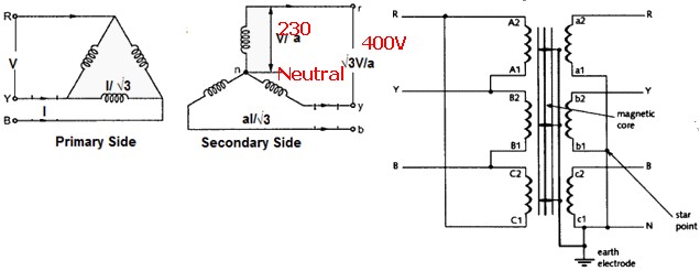
It is usually done with the distribution line that feeds the transformer with a triangle connection (or \$ \Delta \$), and the user connected to each phase of a star connected transformer with neutral.

The current will not flow on the other two phases and thus the load will not change the voltage on the other two lines of the secondary.

Delta-Star

For reference, I got this picture from prof. Franco Mastri slides.

\$\endgroup\$
6
  • \$\begingroup\$ Correct that most distribution transformers are delta-qye (delta HV, wye LV.) Incorrect that single-phase loads on the LV translate to balanced loads on the HV. \$\endgroup\$ Commented Dec 17, 2013 at 11:32
  • \$\begingroup\$ I did not say it balances the load, but that the current will not flow on the other primary or secondary coils, thus keeping the voltage on a single phase of the secondary without fluctuations due to other phases loads. \$\endgroup\$ Commented Dec 17, 2013 at 11:44
  • \$\begingroup\$ I'm confused. Can you draw a picture showing the voltages and currents you are talking about? \$\endgroup\$ Commented Dec 17, 2013 at 11:48
  • \$\begingroup\$ I added the picture to the parent answer. \$\endgroup\$ Commented Dec 17, 2013 at 11:57
  • 1
    \$\begingroup\$ Yes, that's the correct thing. A single-phase load on the wye-connected LV windings appears as a phase-phase current on the HV delta windings. This is because amp-turns have to balance between windings on the same magnetic core. \$\endgroup\$ Commented Dec 17, 2013 at 11:58
3
\$\begingroup\$

The primary / high voltage side of the system is capable of handling unbalance phase currents, but for optimum resource use they should be balanced. eg if each phase has a maximum allowed load of say 1,000A then if the actual currents are 1000, 900, 1100 you have to reduce the overall load to maintain max current at <= 1000A so you scale down by a factor of 1000/1100 = 0.9091 in each phase giving 909, 818 , 1000 amps or a total of 2727A rather than the 3000 notional maximum so power handling is about 91% of what it should be.

If you feed three phases with no neutral to a delta connected transformer primary side and connect the three output phase windings in star mode you get a neutral (centre point of the delta) plus 3 x phases. The secondary loads need to be balanced if balanced primary phase currents are required. Thusly:

enter image description here

\$\endgroup\$
2
  • 1
    \$\begingroup\$ On the secondary side the "difference" between different phase loads flows back via the neutral. Where does it go on the primary side? \$\endgroup\$
    – sharptooth
    Commented Dec 17, 2013 at 11:36
  • \$\begingroup\$ Ignore my previous comments; I misunderstood your post. "Unbalance" has connotations of "earth fault" for me as a protection engineer. \$\endgroup\$ Commented Dec 17, 2013 at 12:00

Your Answer

By clicking “Post Your Answer”, you agree to our terms of service and acknowledge you have read our privacy policy.

Not the answer you're looking for? Browse other questions tagged or ask your own question.