1
\$\begingroup\$

Looking at these instructions for wiring up a LED matrix ( http://oomlout.com/8X8M/8X8M-Guide.pdf ) I see that they tell me to put the resistors that limit the current through the LEDs on the cathode (output) side of the LEDs.

Is there any reasons for this preference? Could I not put the resistance on the anode side instead?

\$\endgroup\$
1
  • 3
    \$\begingroup\$ I think the better question would be "why do you think that's the only way to do it"? \$\endgroup\$ Commented Dec 20, 2013 at 4:50

3 Answers 3

7
\$\begingroup\$

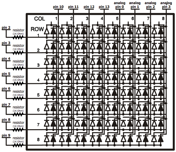
In a LED matrix you're either scanning rows or columns. If you're scanning columns the resistors have to be on the rows, and vice versa.

Scanning columns as is done here means that one column at a time becomes active. Then for each LED in that column you have a corresponding resistor on the rows connection.

Regarding Michael's comment: if you would put the resistor on the scanning side (here the columns) then you'd have 1 resistor for a complete column, the one you're driving at that moment. Then the brightness of the LEDs will depend on the number of LEDs you have on. If you have 1 LED on it will shine 6 times brighter than when you have 6 LEDs on.

\$\endgroup\$
2
  • \$\begingroup\$ It still doesn't matter which side the resistor is on... just nicer to have it on the side with fewer pins (8rows vs 16columns) \$\endgroup\$
    – Michael
    Commented Dec 20, 2013 at 9:39
  • \$\begingroup\$ @Michael - that's not true. If you have it on the scan side you have 1 resistor for 8 LEDs, and then the brightness will vary with the number of LEDs on. \$\endgroup\$
    – flup
    Commented Dec 20, 2013 at 10:23
2
\$\begingroup\$

@Connor Wolf is correct, they technically could be on either side.

From what I have seen on that datasheet the anode of the red and green diodes are wired together; they also talk about only using red OR green. Under this situation you would need less resistors if you connected to the 8 anodes as apposed to the 16 cathodes (red and green).

If you did want the color yellow (both red and green at the same time), then you would get less current through each LED as the resister limits the total current for both.

Having said that, this might be what is desired: a yellow that is the same brightness as the red or green on their own. Had the resistors been on the 16 pins, then you would have a yellow that is super bright, compared to your green and red.

\$\endgroup\$
1
\$\begingroup\$

Why does the resistance of an 8x8 LED Matrix have to be on the cathode?

It doesn't. And in the linked pdf, it isn't. The resistors are on the anode...

enter image description here

\$\endgroup\$
2
  • \$\begingroup\$ Downvote without comment for pointing out that the OP read the schematic wrong? Really now? Ha. You're funny. \$\endgroup\$
    – Passerby
    Commented Dec 20, 2013 at 16:30
  • 1
    \$\begingroup\$ I'm the OP and I DIDN'T downvote this. Yes, you're right. The schematic doesn't show them on the cathode. And that's why I'm confused because the instructions definitely do say to do it that way. \$\endgroup\$
    – interstar
    Commented Dec 21, 2013 at 10:28

Your Answer

By clicking “Post Your Answer”, you agree to our terms of service and acknowledge you have read our privacy policy.

Not the answer you're looking for? Browse other questions tagged or ask your own question.