1
\$\begingroup\$

Hey everyone I'm working on a project where I want to be able to power a thin mini-itx motherboard two different ways. Here is what I'm trying to do:

19V battery will be connected to a relay which is connected to the DC input of the motherboard. The port for the power adapter will also be connected through a relay to the DC-IN of the motherboard and to the charging port of the battery. When the adapter is present the adapter relay is closed and the battery relay is opened. When no adapter is present it closes the battery relay and opens the adapter relay. The goal being that the motherboard always has power and I can charge the battery without discharging the battery at the same time since the power adapter can handle both powering the motherboard and charging the battery.

Since the battery voltage will vary based on its charge i'm concerned that there may be short periods of time where a <19V battery will be connected to the constant 19V power adapter.

So my questions are:

In the case of a <19V battery being connected to the 19V power adapter do I need to worry about current flowing back into the battery? The battery has both a charging port and a output port. I'm not really sure what electronics are present on the output port. Maybe use Diodes to prevent current flowing back into the output port of the battery?

Do you think that when a adapter is connected I could switch the battery relay off and the adapter relay on fast enough to not interrupt power to the motherboard? This question somewhat effects the one above. Because I don't really have a feel for how much time I have. I don't have that much experience with relays. I was thinking of using a microprocessor to control the relays in which case I could disconnect the battery relay first then milliseconds later activate the power adapter relay which should mitigate the problem of connecting the adapter and battery together. However, I'm not really sure if that will be fast enough to maintain power to the motherboard.

Lastly do you see other concerns with this method that I have not yet thought of? Mainly safety concerns for the equipment.

Hopefully this is understandable. First time posting this type of question on a board.

Thanks everybody.

\$\endgroup\$
1
  • \$\begingroup\$ Circuit lab is built into this site. The commercial version is for $ but the in-site one is free to use. \$\endgroup\$
    – Russell McMahon
    Commented Feb 10, 2014 at 6:45

2 Answers 2

2
\$\begingroup\$

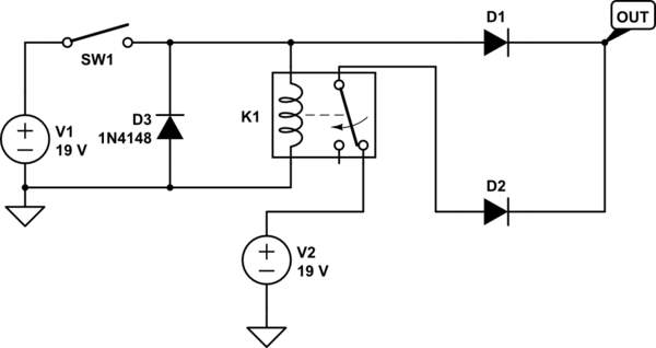
This circuit may do at least part of what you want. V1 is the adapter and V2 is the battery.

D1 and D2 prevent current from flowing back to either source. When S1 is closed (before the relay opens), the diodes D1 and D2 feed along the higher of the two sources to the output. When the relay opens, the battery (V2) is disconnected so even if it is higher than the adapter it will not be drained. It does not matter how long the relay takes, since the diodes will allow one or the other source to power the board during the transition.

There's nothing here that would allow the battery to be charged- not enough information, so this is a yet incomplete answer.

schematic

simulate this circuit – Schematic created using CircuitLab

\$\endgroup\$
4
  • \$\begingroup\$ Hey thanks. I'm going to to grab that CircuitLab program that it is saying you used. I considered using paint, but I figured that would be worse than none. What is the purpose of D3 in your diagram? For charging I just need 19V into the battery through a different port on the physical battery. I'm thinking just use that off of the switch so when the switch closes it initiates the charging of the battery through the adapter. Short circuiting of the battery should be prevented through D1. Is that logical? \$\endgroup\$
    – user36927
    Commented Feb 10, 2014 at 0:27
  • \$\begingroup\$ D3 is there to deal with the relay coil inductance... so the switch doesn't spark. Your conclusion is logical, but I don't have 100% confidence. \$\endgroup\$ Commented Feb 10, 2014 at 0:30
  • \$\begingroup\$ Is part #1N4148 a suggested diode or was that a default part# added by CircuitLab? Really appreciate you taking the time to look at this. \$\endgroup\$
    – user36927
    Commented Feb 10, 2014 at 0:39
  • \$\begingroup\$ Why not both! It should work for any reasonable relay. \$\endgroup\$ Commented Feb 10, 2014 at 0:40
1
\$\begingroup\$

If you use a changeover relay there will be no chance that the two power sources can become connected to each other BUT there will be a small time period when "switching" that no supply is connected. This is going to be in the order of about 10 milli-seconds so maybe, if you can calculate the current needed by the motherboard you can use a capacitor to "hold-up" the voltage for that short period in time.

Alternatively there should be no problem putting diodes across each contact so while the relay contact is in motion, the larger of the two supplies will "fill the gap": -

enter image description here

Once the relay contact has moved to its resting position there will be no voltage drop across the diode because it is shorted by the relay contact.

\$\endgroup\$
1
  • \$\begingroup\$ Thanks for this input. I have a few options now to consider. I appreciate everyone's help with this. If other things come up as I go about implementing this I'll definitely be coming back. \$\endgroup\$
    – user36927
    Commented Feb 12, 2014 at 4:38

Your Answer

By clicking “Post Your Answer”, you agree to our terms of service and acknowledge you have read our privacy policy.

Not the answer you're looking for? Browse other questions tagged or ask your own question.