3
\$\begingroup\$

I would like to mount a TSAL6400 led on a single AA size battery box, with a simple ON/OFF switch. My problem is that the LED needs exactly 1.35V to function at its rated brightness. At this voltage it uses 100 mA current.

I would like to use Sanyo Eneloop batteries. I've measured them and they have 1.405V one day after charging. I think they will drop to about 1.395V @ 100mA.

I've followed the LED tutorials, which all say I have to wire a resistor in serial with the LED. My problem is that if I calculate, that resistor needs to have (1.4-1.35)/0.1 = 0.5 Ohm resistance.

My question is that what would you recommend me to do this project? I would like to make the box as little as possible, I'm planning on mounting everything directly on a single AA box.

  • Shell I use two 1 Ohm resistors in parallel, to get a 0.5 Ohm resistor?
  • Can I possibily use some micro turn potentiometers for my problem? It would be the best solution, as then I could just use different batteries, as all I would need to do is to set it after changing batteries. I am mostly interested in this solution. Can someone explain to me what is the best way to get 1.35V from 1.4V-1.6V sources using a simple potentiometer?
  • Maybe it's an overkill, and I really don't know how to use them, but can I use a voltage regulator for this purpose? I mean is there a voltage regulator which is small and can provide as little as 0.4V drop?

UPDATE: I've made some measurements on my LED:

  • 1.184 V - 12 mA
  • 1.315 V - 75 mA
  • 1.345 V - 93 mA
  • 1.357 V - 100 mA
  • 1.380 V - 110 mA

The last one is when I connected it directly to a Eneloop AA battery. By definition it's overdriving, but I don't know how dangerous it is for the LED. LED measurement

\$\endgroup\$
1
  • 1
    \$\begingroup\$ A AA battery's capacity is between about 1V and 1.4V. You need a higher voltage to get any battery life and maintain 100mA. Two AA's will drop from 2.8V to ~2V: 2.8V/110mA=25ohm; 2.0V/90mA=22ohm -- so about 20ohms, in series with battery ESR, will do it, and actually use the whole battery. \$\endgroup\$
    – tyblu
    Commented Feb 17, 2011 at 3:02

7 Answers 7

2
\$\begingroup\$

By coincidence I was looking for a bycycle dynamo operated LED lamp. White LEDs require about 3.6V, but because the supply varies from the speed you cycle (6V max, AC) I had to put a bunch of electronics in there for it anyway. Furthermore I wished high effiency, I don't want to be cycling for a resistor converting my power into heat.. So I started looking.

Also note that if you get a 1.4V battery, if you drain it, the voltage will slowly drop to about 1V. At 0.8V it's completely dead. You may want to consider to have a working product at 1.2V or 1.1V for example, also if you want to support rechargeable batteries.

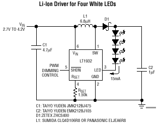
For that you really need a DC/DC converter to boost a voltage up. The LT1932 is probably even more suitable for your purpose. It converts a low voltage to a constant current (which you need for a LED). It's a bit expensive (because 1) it's linear technologies, 2) you're trying to do something low-voltage), but it is able to drive a single LED from 1V. It also has a SHDN pin so you can control it:

LT1932 typical circuit

It can drive several white LEDs (they require over 3V drop each) from 2V input. This figure shows 4 white LEDs, so that's why it needs 2.7V minimal. I don't know how it will behave if you put only 1 LED in there, but I think it will work just fine.

All you need for this driver is shown there. Rset sets the current through the LEDs(in the datasheet is probably a table). It drives the LEDs in this example with 15mA. And as said, LEDs are controlled by current not by voltage. The resistor you normally use only sets a 'fixed' current (for a certain voltage you apply on the system). This regulator is set to a certain current with the resistor Rset, and then you're done. If you put another LED in series, it will adjust the voltage so the current stays the same. Ofcourse, this has limits, but you won't reach that I suppose.

There are more of these IC's and are quite handy. You probably find more examples that are cheaper, but might not be able to work from 1V.

\$\endgroup\$
2
  • \$\begingroup\$ Wow, thank you for this answer. I understand it so much better from this. My question is that is it actually boosing to 14.4V in this example? From a 1V battery source? Does it work in theory the same as what I do when I'd start raising the voltage with a current meter in my hand and stop when the current reached my goal? What are parts C1, L1, D1, C2 doing? Do I need them for it to work? \$\endgroup\$
    – hyperknot
    Commented Feb 22, 2011 at 2:02
  • \$\begingroup\$ 14.4V might be a bit too high for it, but theoratically it will try to act as a current source (not a voltage source). C1 and C2 are added for stability of the regulator. L1 and D1 are there because it is a switching regulator (a DC-DC converter). To understand more about a boost (step-up) converter, read on wikipedia: en.wikipedia.org/wiki/Boost_converter It's quite a 'complex/long' story about how they work. \$\endgroup\$
    – Hans
    Commented Feb 23, 2011 at 14:34
5
\$\begingroup\$

Use a switching boost converter to, say, 3V. The output will be regulated, so you will be able to get a stable 100 mA through the LED with a suitable resistor, and the battery will last much longer than if you connected it directly to the LED and resistor.

\$\endgroup\$
5
  • \$\begingroup\$ I've never used such a thing. Are you talking about something like this TPS61015? It looks a bit complicated to me, for example why does it have 10 pins? Why isn't it just Vin, Vout, GND? \$\endgroup\$
    – hyperknot
    Commented Feb 17, 2011 at 0:40
  • \$\begingroup\$ That's the sort of thing. Because it's boosting the voltage it requires an inductor as well as other parts. You don't actually have much choice! \$\endgroup\$ Commented Feb 17, 2011 at 1:07
  • \$\begingroup\$ I would really like to keep it super simple. I'll need to make a couple of them and use them for active markers for an IR camera. I think I'll stay with resistors. \$\endgroup\$
    – hyperknot
    Commented Feb 17, 2011 at 1:50
  • 1
    \$\begingroup\$ @zsero, You will still need current-limiting resistors, even with a boost regulator. You can use two batteries instead. \$\endgroup\$
    – tyblu
    Commented Feb 17, 2011 at 2:56
  • 2
    \$\begingroup\$ If you're going to build a switcher, build a constant-current one and don't worry about the voltage. \$\endgroup\$
    – markrages
    Commented Feb 21, 2011 at 20:03
4
\$\begingroup\$

The simplest circuit you want is commonly called a "Joule thief", which consists of a resitor, NPN transitor, and a hand-wound inductor. Such a circuit will allow you to pull useful current out of a single AA, AAA, etc battery even when the voltage is far below the LED's threshold voltage. Not sure this will generate a full 100mA though-- this will depend on the inductor and resistor values.

Schematic: http://www.prc68.com/I/JouleThief.shtml

References:

http://www.emanator.demon.co.uk/bigclive/joule.htm

http://www.instructables.com/id/Make-a-Joule-Thief/

\$\endgroup\$
1
  • \$\begingroup\$ Thanks for this idea, in terms of size and complexity this is the closest one to what I'm thinking! But I still don't understand if this has any kind of limit for either voltage or current. I mean it looks like a nice device for saving the batteries, but I would still need to use something to limit the voltage to 1.35 V no matter how the battery is changing, do I not? \$\endgroup\$
    – hyperknot
    Commented Feb 18, 2011 at 3:06
1
\$\begingroup\$

LEDs need current, not voltage. When an LED is conducting it imposes a certain voltage at its terminals but the current that flows through is conditioned by a "conditioning circuit" (which can be a simple resistor in series). You are right, you need 0.5Ohm resistance (which, just like you said, you can get with two 1Ohm resistors in parallel) but once is a very small value it probably will work well without it.

If you want to turn led ON/OFF maybe the use of a transistor should be a better option. The transistor works as a LED drive.

\$\endgroup\$
3
  • \$\begingroup\$ I've tried connecting it directly to the AA battery and it resulted in 1.380 V - 110 mA. Do you think it's dangerous? \$\endgroup\$
    – hyperknot
    Commented Feb 17, 2011 at 1:49
  • \$\begingroup\$ @zsero It will be dangerous when youtry and put an alkaline, lithium, or NiZn battery in your circuit, or maybe even with freshly charged NiMHs. With diodes, small changes in voltage can result in large changes in current, which is why they need to be driven with a medium- to high-resistance source. Your 110mA at 1.38V might become 400mA at 1.6 volts. \$\endgroup\$
    – Evan Krall
    Commented Feb 19, 2011 at 11:07
  • \$\begingroup\$ The biggest danger or a small resistance is that a little change in voltage will influence the current. If your resistor drops only 0.1V, it means that a 0.1V increase in supply voltage means double the current (a resistor is liniear, 2x the voltage = 2x the current, assuming the LED stays about the same voltage, which is a safe assumption). A 0.5 ohm obviously takes almost no voltage at all, so a fractional voltage means a dead LED. \$\endgroup\$
    – Hans
    Commented Feb 21, 2011 at 18:16
1
\$\begingroup\$

As Leon Heller says, you will need to boost the voltage to something higher. The 1.35V forward voltage you mention is not an accurate reflection of the voltage you will get with 100mA forward current, but a statistical average.

From the data sheet, it could be as high as 1.6V and as low as ... who knows, the data sheet doesn't say. If we suppose that the distribution is symmetrical, it could be as low as 1.1V, in which case the current you will get with a 1.4V battery and a 0.5Ω resistor could be anything between zero and 600mA.

If you are only building one of these, you might well get a fairly 'average' LED and get a reasonable brightness - but you can't guarantee it.

\$\endgroup\$
2
  • \$\begingroup\$ I have a dozen of those LEDs. I've checked them with my cheap multimeter and in the diode testing mode, it said 1537-1540 for all of them. And the one sample I've measured is precisely 0.10 A @ 1.35V, like in the specification. Do you think I really need that complexity? I'd need to make a dozen of them. \$\endgroup\$
    – hyperknot
    Commented Feb 17, 2011 at 2:01
  • 1
    \$\begingroup\$ @zsero - It could be that the LEDs' characteristics are very tightly controlled at manufacture and that the datasheeet is over-cautious. What you have done is a "select-on-test" process which used to be common in industry but is too labour intensive these days. It's still perfectly valid though. If you have tested a bunch of LEDs and they work in your circuit, use them. My answer was based on experience. I have seen circuits where insufficient voltage has caused wide variations in brightness. \$\endgroup\$
    – MikeJ-UK
    Commented Feb 17, 2011 at 11:14
1
\$\begingroup\$

You don't always have to have a resistor. They are there to limit the amount of current going through the LED. LEDs have a maximum current rating, and can also handle a higher current if you PWM them for short periods of time. Anyhow, if your battery has a limited output current, you don't even need the resistor. For example, with LED throwies, you typically use a coin cell. I can't remember the exact amount, but I think they max out at 20mA, which is well within the rating of most LEDs.

\$\endgroup\$
3
  • \$\begingroup\$ Uhm, my AA battery is capable of supplying 4A, so it's not really a useful limit in my case. But I tried it connecting directly to the battery and it resulted in 1.380 V - 110 mA. Do you think it's too much? \$\endgroup\$
    – hyperknot
    Commented Feb 17, 2011 at 2:03
  • \$\begingroup\$ according to the datasheet, it should work, I would still use a resistor for longer life and better battery performance electronics.stackexchange.com/questions/8182/… \$\endgroup\$
    – jsolarski
    Commented Feb 17, 2011 at 4:44
  • \$\begingroup\$ @zsero sorry, I should have boldfaced and italicized the if when I was talking about the output current limit. :) I would definitely use a resistor. LEDs will not last long if constantly driven with 100mA. You really need to PWM the LED in such a situation. \$\endgroup\$
    – Dave
    Commented Feb 17, 2011 at 5:08
0
\$\begingroup\$

The 1.35V indicates to me that it is an infrared or IR LED. Instead of a voltage regulated circuit and a resistor, you should use a current regulated circuit. In its simplest form this is a chip with a few components such as an inductor, resistors and capacitors. One maker of these is Maxim.

\$\endgroup\$
1
  • \$\begingroup\$ Can you provide links. \$\endgroup\$
    – Kortuk
    Commented Feb 21, 2011 at 21:51

Your Answer

By clicking “Post Your Answer”, you agree to our terms of service and acknowledge you have read our privacy policy.

Not the answer you're looking for? Browse other questions tagged or ask your own question.