1
\$\begingroup\$

EDIT: The requirements in the question below appear to be practically unsolvable, but happily after a bit of digging I actually found an alternative equivalent RS232 device which runs off a 3.7V Li-Po instead of 3.0V AAAs.
Moral of this story: hold off purchasing for as long as you can - it can prove extremely beneficial :)
I've asked a new question for my new set of requirements.


I need to connect a Wi-Fi/RS232 module to a low-powered monitoring device which needs to periodically fire up, "ping" a server, then shut down again. For maximum portability, I'd like to power the Wi-Fi module via the pair of AAA batteries built into the device itself.

This decision was considered viable based on the fact that the device in question is very low-powered and takes just over a month to drain its batteries under normal use, and the fact that the Wi-Fi module will only power on for a few moments at a time and will generally use relatively small amounts of power. I'm very confident that I'll be able to get at least a few days' worth of battery life with the Wi-Fi module attached, and it won't be a problem to put new rechargeables in the unit every so often.

Now, the Wi-Fi module I've selected draws 3.3v at a peak of 250mA, so I need a step-up converter to run it off two AAAs. However:

  1. The converter needs to fit inside a compartment 50x54mm in size, approximately 4-5mm thick. For what it's worth, this area is insulated, so insulation thankfully doesn't need to be taken into account.
  2. The unnecessity of insulation aside, the step-up converter needs to produce virtually zero EMI/RFI due to the electromagnetically sensitive medical environment the device will be used in, which won't tolerate even low levels of continuous EMI/RFI radiation particularly well (although short Wi-Fi bursts will be fine).
  3. I've never dealt with step-up converters before, and I'm unsure what effects the converter's electrical behavior/characteristics might have on the other electronics (a CPU, etc) in my RS232 device. What might I need to consider in this regard?
  4. The Wi-Fi module draws 8mA when idle, which would kill a pair of AAAs fairly quickly. I can control the serial device's DTR line like a GPIO, so it should be possible to set DTR high or low to electrically switch the step-up converter on or off. I have absolutely no idea how to go about this electronically however, although I can say that the RS232 device uses TTL signal levelling, instead of standard RS232 voltage levels.

I must admit that SMD component-based solutions wouldn't work out for me very well; I have passable non-SMD soldering skills, but I've never worked with SMD components, and if possible I would like to build this device myself, preferably successfully.

If an inexpensive premade power converter module exists that meets the above requirements, that would be a very attractive option.

Alternatively, since the adaptor/converter won't be being moved after it is fitted, directly soldering non-SMD components' legs to each other would also be an acceptable solution.

\$\endgroup\$
4
  • \$\begingroup\$ The recommended way to mark a question as solved / completed etc is either to accept the answer you found most useful, or if you solved the problem yourself you can post your own answer and accept that. \$\endgroup\$
    – PeterJ
    Commented Mar 19, 2014 at 23:23
  • \$\begingroup\$ @PeterJ: The question was effectively "unsolvable", as mentioned at the start of the question. I was provided with useful information but not a direct answer to my specific question. How does one typically respond on here in a situation like that? \$\endgroup\$
    – i336_
    Commented Mar 19, 2014 at 23:26
  • \$\begingroup\$ I'd probably either mark the answer that convinced me most of that as accepted, or otherwise write an answer that highlights why it couldn't be solved. While the title edit might encourage others not to answer at the moment the question will be bumped occasionally by "community" because it looks unanswered from the system's point of view. \$\endgroup\$
    – PeterJ
    Commented Mar 19, 2014 at 23:31
  • \$\begingroup\$ Thanks, that makes a lot of sense. :). Added new answer with explanation. \$\endgroup\$
    – i336_
    Commented Mar 19, 2014 at 23:34

3 Answers 3

5
\$\begingroup\$
  1. Size constraints: The challenge would be the 4-5mm height, rather than the other two dimensions: A boost converter will typically require an inductor, likely to be the tallest part.

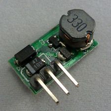
    For instance, this prebuilt 1 V --> 3.3 V boost converter module is 12x22mm, but the inductor on it is 6 mm tall:

    Boost converter

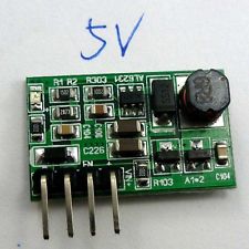
    This example does not offer an enable pin, though - My cursory search shows several 5 Volt and 12 Volt boost converter modules with an enable pin, but not for 3.3 Volt output.

  2. EMI constraints: This is a tougher problem. A typical boost converter works by switching currents on and off using an oscillator, hence even with the filter capacitors on the board, there will be some EMI at the oscillation frequency and its harmonics. These modules certainly are not medical-grade electronics. "Virtually zero" is virtually impossible.

    An option is to use a 5 Volt boost converter like this one, followed by a low drop-out, low-ripple linear regulator to produce the desired 3.3 Volts. The 3.3 Volt rail then will have negligible noise.

    Boost controller with enable pin

    Direct EMI radiation, especially from the boost converter's inductor, will still be an issue. To address this, shielding the entire assembly with a metal box or mesh would help. Only your own testing will reveal whether this serves the purpose sufficiently.

  3. Microcontrollers typically work perfectly fine even with fairly noisy (50 to 100 mV ripple) power rails from boost converters. Also, a hybrid incorporating an LDO, as suggested above, addresses this issue completely.

  4. The "enable" pin in the 5 Volt boost converter suggested above could be toggled by the DTR pin - but then how would you be supplying power to the serial device when the boost is off?

    For similar applications, I have used an unregulated supply (just capacitors) from the AAA cells into a minimal microcontroller such as the ATtiny85, and used the microcontroller's output pins to toggle the boost controller supplying the rest of my device. Consider whether this works for your design.

\$\endgroup\$
3
  • 1
    \$\begingroup\$ Hmm, at 250mA, an inductor-less charge pump regulator would work, making size issues moot. \$\endgroup\$
    – Passerby
    Commented Mar 17, 2014 at 0:29
  • \$\begingroup\$ Anindo Ghosh: Thanks for that extensive information - definitely filed away :) Once I read that EMI would be an issue (adding shielding inside the constraints of the compartment I have to work with would be a little difficult), I did some more research and have found an alternate solution (the link can be found at the top of my question). @Passerby: That's very interesting... for reference, would this mitigate the level of radiated EMI? \$\endgroup\$
    – i336_
    Commented Mar 19, 2014 at 23:12
  • \$\begingroup\$ @i336_ a charge pump is a different type of switching regulator, switches more often, but doesn't use a coil which radiates more. EMI would need to be evaluated in either case. The suggestion was in terms of space. \$\endgroup\$
    – Passerby
    Commented Mar 20, 2014 at 3:39
2
\$\begingroup\$

Could you use a 'two step' approach?

Use a cheap and small microcontroller with (non-wifi) wireless radio, and then a 'repeater'-like device that forwards the 'ping' to Wifi?

You could then use a JeeNode Micro ATMega based radio module and a PC, laptop or even something like a Raspberry Pi with a radio receiver and a Wifi module.

The JeeNode micro is really low power and can run of a coin cell or two or three AAA/AA batteries. If the 'ping' is small and only very infrequent it can run for months on a coin cell.

All these use standard off the shelf controllers (ATMega / ATTiny) and radios (Hope RF) and can be cheaply built on breadboard/perfboard if needed.

\$\endgroup\$
1
  • \$\begingroup\$ That's very interesting - I'll probably use something like that at some point in the future - but I want the device itself to be extremely portable: put it in my pocket, forget it's there, and it does its thing. A "middleman" would mean the Wi-Fi part would still need to sit in my pocket as well as the monitoring device... it wouldn't be ideal. \$\endgroup\$
    – i336_
    Commented Mar 19, 2014 at 23:30
0
\$\begingroup\$

After learning how it's virtually impossible to obtain practically zero RFI/EMI from a switching design, I actually did a bit more research and turned up an alternative (equivalent) target device which runs off 3.7v instead of 3.0v, so all I need to do is remove 0.7v now.

I've asked a new question for my new set of requirements.

\$\endgroup\$
4
  • 2
    \$\begingroup\$ Don't get me wrong, but I noticed nobody upvoted any answers here and in at least another question you asked, not even you. And some are pretty good. So, please, consider at least upvoting the answers you've been given if they were a bit helpful to you. That will give reputation points to the users who have answers. That's the only payment they will get for helping you. Also, consider accepting their answer instead of yours, even if your reqs changed, that's an even greater contribution. To upvote, click the up arrow next to the vote count, on the left-hand side of the questions. Thanks!! \$\endgroup\$
    – Ricardo
    Commented Mar 20, 2014 at 0:33
  • \$\begingroup\$ Ironically, I tried to upvote both answers, but I initially couldn't because my reputation was only 11 on here a couple of hours ago :P (it's 16 as I write this). Both are upvoted now. Also, I realize the significance of accepting a particular answer, and I'm not trying to accept my own answer to gain points or anything (if I even can), but rather because the answers provided don't resolve the question. If there is an elegant way to solve this I'm happy to apply it! :) \$\endgroup\$
    – i336_
    Commented Mar 20, 2014 at 1:45
  • \$\begingroup\$ So sorry. Forgot you need rep to upvote. Sorry about that. It's alright to accept your own answer at times, but in this case I thought you could have accepted the answer that was most helpful, that helped you decide to change your the requirements and just update your question to report your findings and link to your next question. \$\endgroup\$
    – Ricardo
    Commented Mar 20, 2014 at 2:06
  • \$\begingroup\$ But then, if no answer was helpful, not even to show that you can't get away with no EMI, then what you've done is correct. In any case, it's good to know that you care. Welcome to EE.SE. It's great to have you here. \$\endgroup\$
    – Ricardo
    Commented Mar 20, 2014 at 2:08

Your Answer

By clicking “Post Your Answer”, you agree to our terms of service and acknowledge you have read our privacy policy.

Not the answer you're looking for? Browse other questions tagged or ask your own question.