I'm trying to program a Freescale MC12311 transceiver IC which has a 9S08QE32 MCU embedded in it:
MC12311: Sub-1 GHz RF and 8-bit HCS08 MCU with 32KB Flash, 2KB RAM
I'm using a Background Debug Module (BDM) from P&E Micro (USB Multilink Universal); and also the Codewarrior 10.4 software as IDE.
However, the following error occurs each time I try to program/debug/flash/erase the target IC:

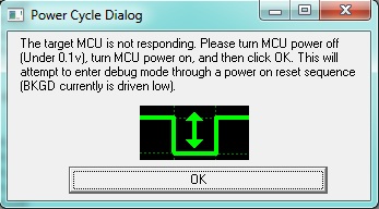
Power Cycle Dialog: The target MCU is not responding. Please turn MCU power off (Under 0.1v), turn MCU power on, and then click OK. This will attempt to enter debug mode through a power on reset sequence (BKGD is currently driven low).
I tried to power off/on the MCU, but there's no success, and it fails to connect to the target board.
I have checked the pins and connections, and everything seems OK. Also, I have checked the BKGD and RESET pins of the 2x3 BDM header, and some activities (high-to-low and low-to-high) are monitored on oscilloscope.
In other hand, I have tried different versions of Codewarrior (10.5, 10.4, 6.3, etc.) and also on different platforms (Win7-64bit, WinXP-32bit, etc.), but the result is always the same: it fails to connect to the target board.
What should I do now? What's the problem?
EDIT
(The following is a list of additional information regarding the troubleshooting steps I've taken to solve this problem, which were not successful.)
I'm using a P&E USB Multilink Universal, and CodeWarrior 10.4 IDE, on Win7 64-bit platform.
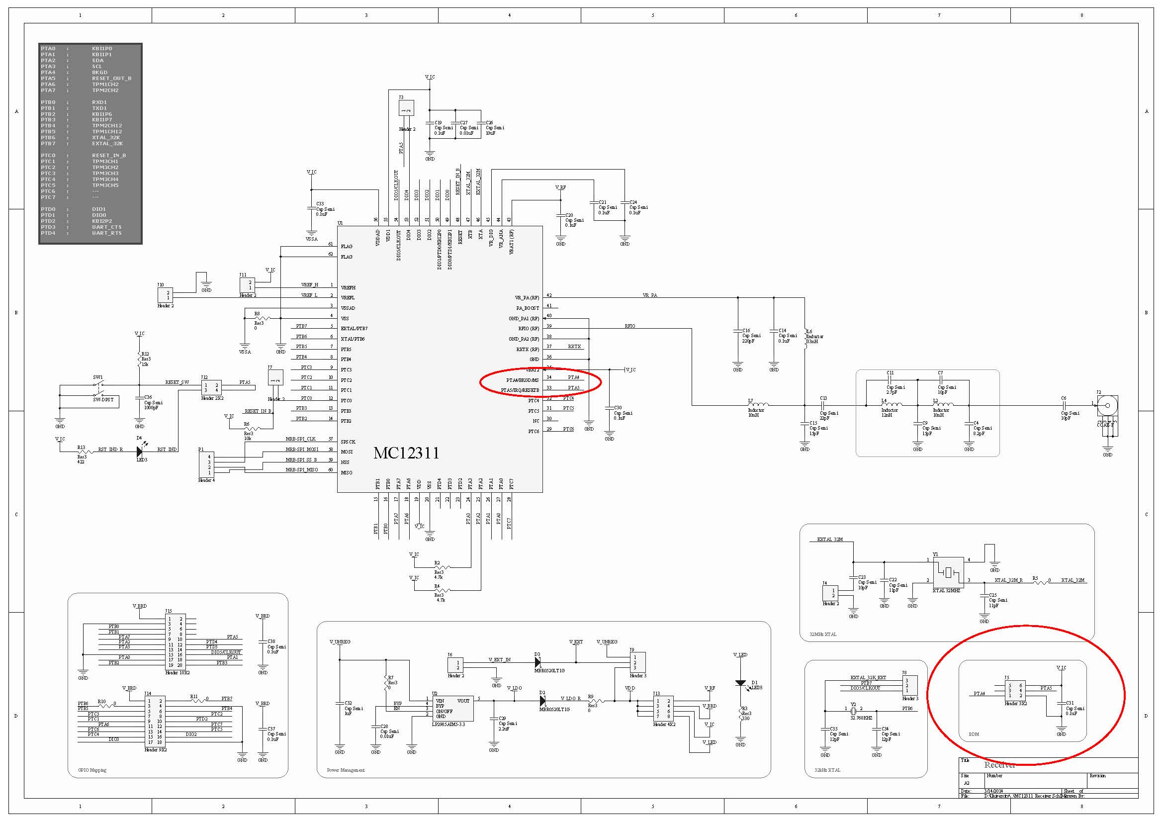
But unfortunately, turning off/on the power doesn't help, and it fails to connect to the target. The following is the schematic of my circuit, in which the red circles depict the BDM header and connections:
(Click on the schematic image to enlarge.)
The following is a list of the related tries:
I've added 10k pull-up resistors to both BKGD and RESET lines; but no success! The same error occurs and it fails to connect to the target.
I try to turn off/on using either the main power supply, power jumpers, reset switch, etc.; but it doesn't matter; again no success!
I checked the pins on the pcb, and everything seems OK. I mean, it seems that it has been soldered without any significant problems.
I monitored both BKGD and RESET pins: some activities (going from low to high, and high to low) are monitored after I press the "erase" button on CodeWarrior IDE.
I tried to monitor the external 32 kHz and 32 MHz crystal resonators, using a 10x probe, with both an analog oscillator and a digital counter. However, no activity is observed, nothing at all! It seems that either the crystals or the respective internal circuits are dead!
The datasheet mentions that "the MCU has an internal crystal oscillator, which is enabled in every power-on-reset, without need for external components". What I understand from this part, is that the program/debug/erase step should be done without need for external crystals. This could mean that even if both of the external crystals are dead, I should theoretically be able to erase the MCU with the help of the internal oscillator. But I don't understand why it fails!
I tried to program/debug/erase this IC using another version of CodeWarrior, such as 6.3, and also on another operating system, such as Win XP, or Win7 32-bit. But again no success!! The same error occurs, and it fails to connect to the target.
There's another circuit board which uses the same MC12311 IC with almost the same components, configurations, and schematic. I tried all the mentioned steps on that board. But unfortunately, no success again! The same errors and the same failures!
I checked the power: I provide 5-6 volt external power supply; it passes through a 3v3 regulator; then it passes through a schottky diode, and the final regulated 3.1 volt powers the IC. It is mentioned in the datasheet that the accepted input voltage range is approximately 2.5 ~ 3.7. So I don't think this "3.1 volt" would cause any problems.
Could this be related to the "clock" sources of the MCU?
I really don't know what to do next to solve this challenging problem! What should I do? I would be really grateful if you give any helpful comments or replies.

