2
\$\begingroup\$

I have a 3 color LED that I'm controlling from an STM32. VDD for my mcu is controlled by a switching regulator set to 3.0v . Unfortunately the forward drop on the the green led is 3.2 volts. This forces me to source current from the battery attached to my board ( 3.8v lipo). So the anode of each led is connected to the battery, and each cathode is connected to a resistor and then an io pin of my SMT32.

If you cruse the SMT32F* reference manuals you'll find out that each IO pin has a set of protection diodes attached (see below). The problem is when I shutdown the Switching regulator it effectively ties vdd to ground. So we have a path from the battery through each of the leds through a resistor finally though the protection diode to vdd which is tied to ground. I need to turn off the switching regulator to conserve battery power.

My question is does anybody know the forward drop on these protection diodes? If its high enough then i don't have to worry about current flowing through the leds and protection diodes to ground. If it isn't I'm assuming I'll have to put a between the mcu and the regulator unless somebody else has a clever soltuion to this problem.
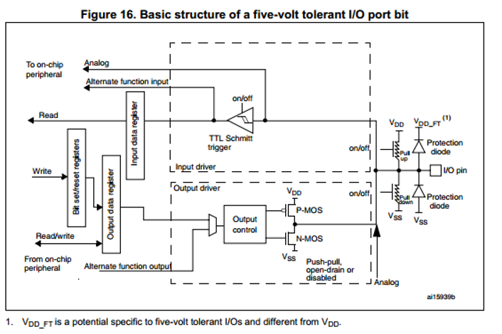
STM32 IO Pin Structure

\$\endgroup\$
3
  • 2
    \$\begingroup\$ Why not use a transistor driver? \$\endgroup\$ Commented Mar 26, 2014 at 4:32
  • \$\begingroup\$ When different supply voltages were used, we will get these scenarios. Absolute maximum ratings give typ forward voltage of diodes on IO's. like -0.3 to VCC+0.5V, SO, lower diode can handle 0.3V and Higher diode handles 0.5V. Based on max battery voltage, LED forward voltage drop we can calculate the current through these diodes Vbat =3.8, Vf of LED =3.2, Vf of Top diode assume 0.5V ---> 3.8-3.2-0.5/Current limiting resistor. Current may be very less...But this is not recommeded. \$\endgroup\$
    – user19579
    Commented Mar 26, 2014 at 8:20
  • 1
    \$\begingroup\$ Keeping in mind your battery voltage will be up to 4.2v when freshly charged, the external transistor/fet driver sounds like a good idea. Also, there may be an unfortunate variation in brightness between a fully charged and an end-of-intended-discharge battery. \$\endgroup\$ Commented Mar 26, 2014 at 14:38

1 Answer 1

1
\$\begingroup\$

My question is does anybody know the forward drop on these protection diodes?

Read the datasheet carefully. The absolute maximum ist usually stated as VCC+X - the X is the forward drop of the diode.

[...] soltuion to this problem.

Switch the LED supply off at the same time, using 2 FETs. Alternatively you could use a N-channel FET to switch each LED.

\$\endgroup\$
2
  • \$\begingroup\$ Good catch, so even in the worst case (freshly charged battery 4.2v) the forward drop between the leds (2.8v for red) and the vdd io protection diode (4v according to datasheet) will be larger than the voltage from the battery. So theoretically I should be able to skip the FET. The board is very small and It's already heavily populated in case your wondering why I'm making such a fuss over a single FET. Thanks! \$\endgroup\$
    – kabla002
    Commented Mar 27, 2014 at 4:56
  • \$\begingroup\$ @kabla002: SN74LVC3G07YZPR \$\endgroup\$ Commented Mar 28, 2014 at 2:17

Your Answer

By clicking “Post Your Answer”, you agree to our terms of service and acknowledge you have read our privacy policy.

Not the answer you're looking for? Browse other questions tagged or ask your own question.