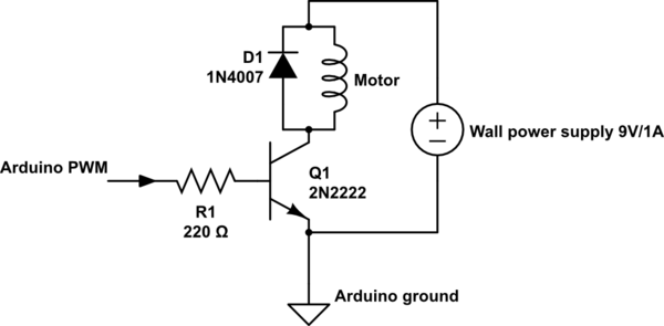
I've been fiddling around with a brushed DC motor, a 2N2222 and an arduino's PWM to get different speeds out of my motor. Now, based on a video tutorial I watched on youtube, It was recommended to put a 1k Ohm resitor between the PWM pin and the base, apparently to protect the arduino in case the transistor screwed up. I did what I was told to do, following this schematic (My power supply is 1.5V and R1 is 1K, not 220)
But the motor would not turn when the microcontroller pin would output 5V ( full duty). So I figured, ights, let me not mess around with my arduino in case that was the problem, so I connected the base, throught the 1k resistor, to the same 1.5V powering the motor...still nothing...put a new 1k resistor...still nothing...so I romoved the 1k Ohm resistor and plugged my base straight to the 1.5v source and the motor started turning.
Can someone please explain to me why that is? From what I've been reading, isn't the voltage at the base what determines the current flowing from the collector to the emmiter? -_- <-- Confused face
