3
\$\begingroup\$

I am currently working on an amplifier circuit for an 8MHz signal (around -40dbm.)

The amplifier is based on an IC chip (LM7171 bin).

The problem is, the amplifier works perfectly individually (correctly gives +20dB gain,) but when we cascade two of them together, it only amplifes +6dB in total.

It is supposed to give +40dB gain. It is probably not a problem of op-amp saturation.

Below is how we cascade our circuit. (VCC=15V, Vee=-15V)
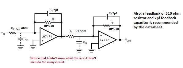
enter image description here

The datasheet is here.

Decoupling capacitor is also connected between the source.


update:

For decoupling, I use 4 capacitors for each amplifier (Vcc=15V, Vee=-15V.)
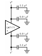
enter image description here

Both op-amp work well individually (without connecting them together.)

When I meassured the midpoint between two op-amps, it gives +20dB gain. This circuit is on a breadboard.


Update2:

(Please note that this is not the circuit I have now, this is what I had before. Notice that in the picture, the two op-amps are not connected together. I can't take a photo of the current circuit because I don't have them with me. But the only change I make is simply connect them together and change the Rg value a little bit).
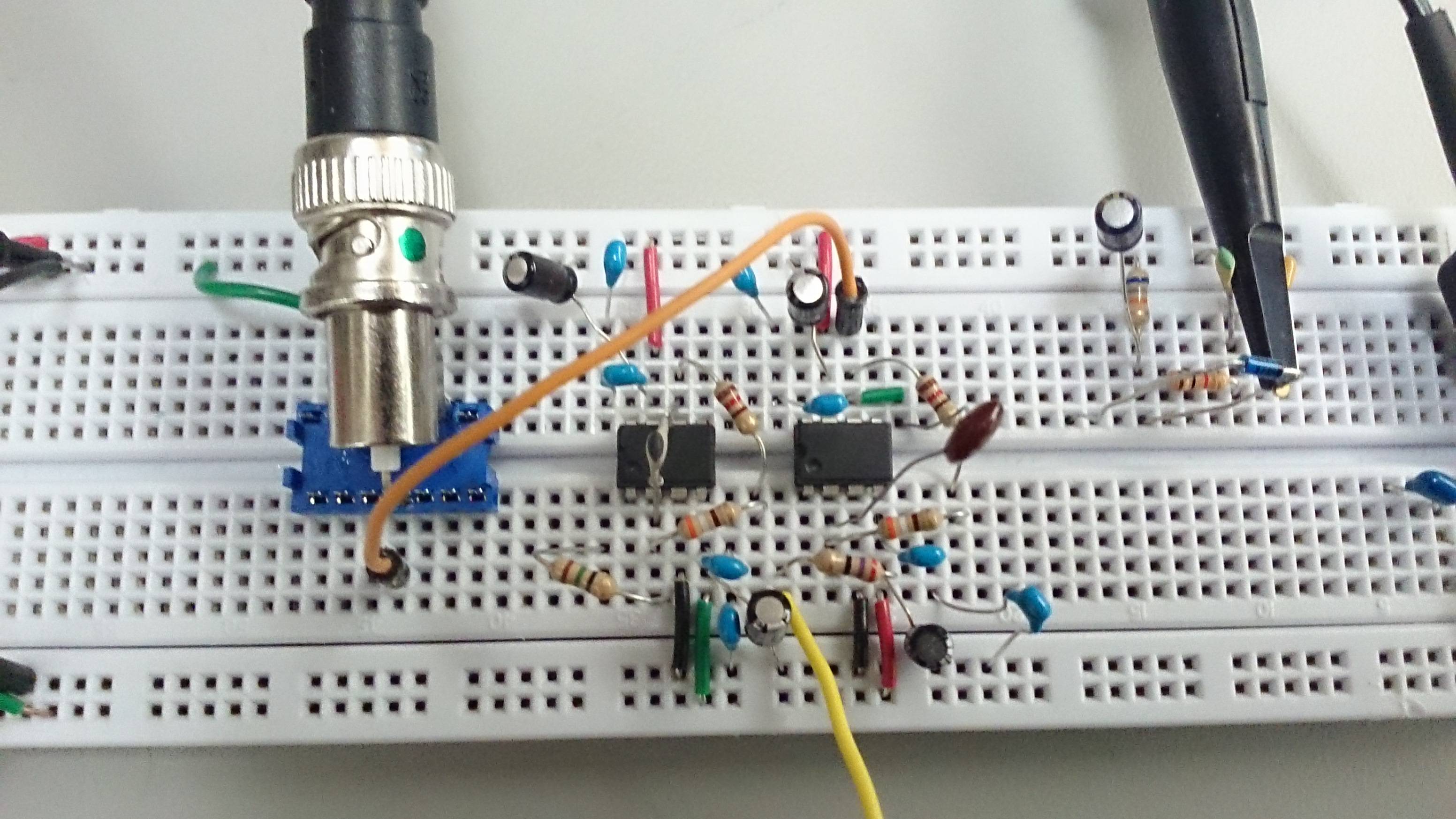
enter image description here

\$\endgroup\$
13
  • \$\begingroup\$ It really sounds like you have a simple wiring error somewhere. Does each of the amplifiers work correctly on its own? \$\endgroup\$
    – Dave Tweed
    Commented Mar 30, 2014 at 16:56
  • \$\begingroup\$ yes,it does. We simply connect the output of the first one to the input of the second one. \$\endgroup\$
    – kuku
    Commented Mar 30, 2014 at 16:57
  • \$\begingroup\$ What sort of power supply decoupling have you used and what sort of construction is the circuit i.e. pcb or breadboard? Also, how have you measured the output signal and if you measured the output signal at the halfway point, does that tally with a single amplifier's gain of 20dB? \$\endgroup\$
    – Andy aka
    Commented Mar 30, 2014 at 16:59
  • 2
    \$\begingroup\$ Also check DC bias voltages at input and both outputs. If first amp had >1.5VDC on its output the second output would simply sit at a supply rail, not provide gain. \$\endgroup\$
    – user16324
    Commented Mar 30, 2014 at 18:11
  • 3
    \$\begingroup\$ If this an example of your general breadboarding technique, it's pretty bad, at least for RF. You have two separate ground busses, but it isn't at all clear how they're connected to each other (if at all). You need to have several direct wires between them, very close to the opamps. Also, what's the idea behind having two of the little blue decoupling caps in series on each opamp power pin? In general, all of your component leads need to be much shorter. Anyway, I'm betting you have a considerable offset bewteen the two ground busses at 8 MHz. \$\endgroup\$
    – Dave Tweed
    Commented Mar 30, 2014 at 18:17

2 Answers 2

1
\$\begingroup\$

Do not cascade them it will be extremely noisy and you lose a lot of dynamic range, instead use a splitter and combiner and use them in parallel to get higher gain. Try using a wilkinson divider for that purpose.

\$\endgroup\$
0
\$\begingroup\$

I can't tell you about any wiring problems you have but you are overloading the output from the first stage with the 51 ohms of the 2nd stage. The data sheet hints at loads between 100 ohms and 1kohm so, try lowering your input signal to see if the gain actually exists at lower levels of amplitude first.

If this doesn't work then try using a 100 ohm input resistor for the 2nd stage and see if results are as you would expect is 34dB gain.

Also try lowering the input frequency to about 1MHz and see what happens.

Also check your power supply decoupling capacitors.

\$\endgroup\$
2
  • \$\begingroup\$ Are you sure that's what's going on here? I haven't bothered to trace out the breadboard (that's what schematics are for!) but I read the schematic as talking about cable impedance, which shouldn't apply for two op-amps right next to each other. What's the characteristic impedance of solderless breadboard? Now, if the OP has gone and tried to do impedance matching with a 51R to ground between the two stages, then yeah, he's going to have problems. \$\endgroup\$ Commented Apr 14, 2015 at 15:24
  • 1
    \$\begingroup\$ Also, I doubt the LM7171 has a problem driving 51Ω anyway. It's an unusually studly op-amp, a small cable-driver, really. I think the real issue is trying to use a 200 MHz IC on solderless breadboard. Madness. \$\endgroup\$ Commented Apr 14, 2015 at 15:40

Your Answer

By clicking “Post Your Answer”, you agree to our terms of service and acknowledge you have read our privacy policy.

Not the answer you're looking for? Browse other questions tagged or ask your own question.