2
\$\begingroup\$

I have a (radial) system with several multi-winding transformers, for instance one 24 MVA 7-winding transformer from 11 kV to 1.92 kV.

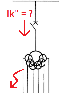
I want to calculate what the short circuit current will be on the primary side, if a 3-phase or a line-line fault occur below one of the secondary windings?
enter image description here

For a two-winding transformer, this is quite straight forward.

However, I don't know what values to use in the multi-winding case. The capacity of each of the 6 secondary windings are 4 MVA. My intuition tells me the secondary winding will be the limiting factor.

Assuming the short circuit capacity is 100 MVA, and the transformer impedance is 10%, what will the short circuit current be?

There will be no contribution from the other secondary windings.

I would think the capacity of the secondary winding (4 MVA) is dimensioning, and therefore calculate it this way: (3 phase fault)

\$ Ik'' = 100MVA \cdot\$ \$ 4MVA / 0.1 \over \sqrt3 \cdot (100MVA + 4MVA / 0.1)\cdot 11 kV\$ = \$ 1.5 kA \$

But it could also be the primary (24 MVA):

\$ Ik'' = 100MVA \cdot\$ \$ 24MVA / 0.1 \over \sqrt3 \cdot (100MVA + 24MVA / 0.1)\cdot 11 kV\$ = \$ 3.7 kA \$

But then again: It might be something completely different, since a 7-winding transformer is quite different from a 2-winding. Any views on this? Any literature maybe?

Not of any relevance: Vector group: Yd11y0d11.20d0.20d11.40d0.40

\$\endgroup\$
5
  • \$\begingroup\$ Can you post the transformer's full nameplate information (i.e. photo of the nameplate) or the impedance data from its factory testing records? \$\endgroup\$ Commented Apr 15, 2014 at 1:22
  • \$\begingroup\$ I am also really, really curious as to what this transformer is even used for. \$\endgroup\$ Commented Apr 28, 2014 at 9:58
  • \$\begingroup\$ @Li-aungYip, it's feeding a large VSD. The main reason why there are many windings is to eliminate harmonics. I'm afraid I don't have time to go into details and find proper references right now (I'm not even sure I can find any publicly available documentation). There are however some references on this for three-winding transformer, it's much the same, only on a larger scale. I wish I could share more... \$\endgroup\$ Commented Apr 28, 2014 at 11:02
  • \$\begingroup\$ I'm aware of the way it works. The more phase-displaced voltage waveforms you can get, the more 'pulses' you can have on your VSD. Normal three-phase supply gets you six pulses. Three-winding transformer (two phase-displaced three phase supplies) gets you 12 pulses. I imagine you're using a 36-pulse VSD. Am I warm? :P \$\endgroup\$ Commented Apr 28, 2014 at 12:57
  • \$\begingroup\$ @Li-aungYip Yes, you're spot on. It's feeding an ABB ACS5000 drive. \$\endgroup\$ Commented Apr 28, 2014 at 13:00

2 Answers 2

4
\$\begingroup\$

I've never seen a seven-winding transformer but I have dealt with three-winding transformers.

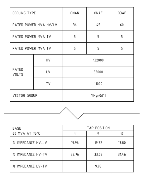
The nameplate information for one particular three-winding transformer is as per below. (Graphic redrawn from photo to avoid showing the full extent of the very large nameplate.)

enter image description here

The impedances given are all on 60 MVA base. In this case tap no. 5 is the principal tapping, so consider the impedances as HV-LV 19.32%, HV-TV 33.08%, LV-TV 9.93%.

The impedance quoted for each pair of windings is with a voltage applied to the first winding, the second winding shorted, and all other windings open circuit. Refer IEC 60076.1:2005 Power Transformers - Part 1: General:

enter image description here

Therefore, assuming --

  1. your transformer nameplate gives impedance for each individual winding
  2. the testing was done as described above
  3. your fault condition will be three phase fault on one winding, other windings effectively open circuit

-- your fault current depends only on the impedance from the HV winding to the particular winding under fault.

In this example, a three-phase fault on the 33 kV winding would produce a maximum three-phase fault current of 60 MVA ÷ 19.32% ÷ 33000 V ÷ √3 = 5.43 kA. A three phase fault on the 11kV winding would produce 60 MVA ÷ 33.08% ÷ 11000 V ÷ √3 = 9.51 kA.

\$\endgroup\$
2
\$\begingroup\$

The transfer impedance determines SC current along with rated current of primary side.

The 10% means the short circuit will present 1/10% or 10x rated current with a secondary short, regardless where the loss is highest.

BTW This is also how Hot Spot Temp. Rise tests are conducted using a shorted output but reduced input to match VA capacity. Ref IEC 60076-7

\$\endgroup\$

Your Answer

By clicking “Post Your Answer”, you agree to our terms of service and acknowledge you have read our privacy policy.

Not the answer you're looking for? Browse other questions tagged or ask your own question.