1
\$\begingroup\$

I am seeing relays reach their end of life much sooner than expected (and in a catastrophic manner). Specs on the relays are 24VDC 30A SPST NO. I am putting 10A to 20A of resistive load on said relays. They are lasting roughly 35000 cycles under these conditions before failing (speced out at over 250K).

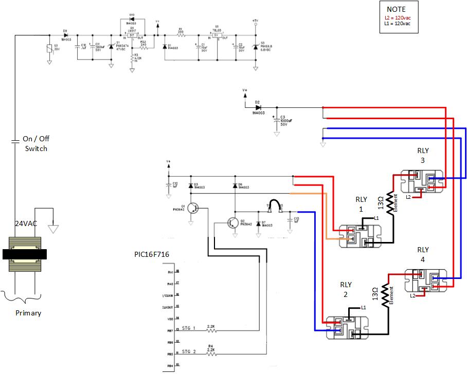
In looking at the design, it has been noticed that instead of breaking "+" or "-" to said relay coils, we're simply letting the power supply "die out" as needed.

In speaking with the applications engineer for said relay MFG, they have no comment on this, no data to present and really nothing to say about it. As far as their concerned, this is untested. I've attached two diagrams to illustrate

Does anyone have experience with this? Anyone have thoughts on this? enter image description here enter image description here
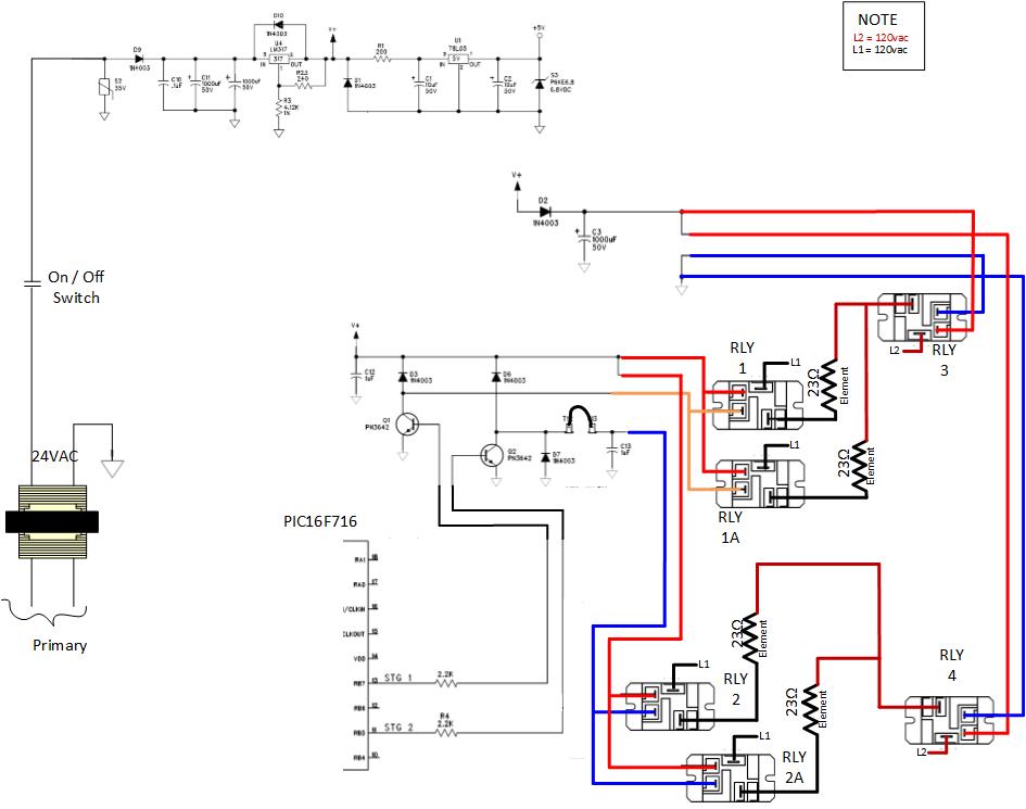
Note: Assume Q1 and Q2 are supplied with base current once +5VDC is available to power the micro

\$\endgroup\$
2
  • \$\begingroup\$ Which relays are failing? What do you mean by "catastrophic"? Welded 'on'? \$\endgroup\$ Commented May 1, 2014 at 16:00
  • \$\begingroup\$ Always relay 1. Once in a while it is relay 1, 1A, 2 and 2A. Relay 3 and 4 have an additional 1000uf cap so they remain energized longer and never open with load on their contacts. By catastrophic I means it melts down and emits a lot of black soot / smoke in the enclosure. I would say the contact melt apart, is the best way to describe it (versus weld shut) \$\endgroup\$
    – becjasl
    Commented May 1, 2014 at 16:14

1 Answer 1

1
\$\begingroup\$

In general it's desirable to allow the relays to switch as quickly as possible to maximize the life. If the (protection?) relays 3 and 4 are welding on due to slow turn off, you can use a more sophisticated circuit to switch them. I suggest a power supply supervisor chip driving a transistor (see below), which will snap on an off abruptly.

Presumably relays 1 and 2 are being switched more frequently and are failing by wearing out. In that case, you should put a resistor or zener in series with the diode to allow the voltage to rise to a good portion of the rating of the drive transistors (taking care not to exceed the SOA). A zener across the transistor is another method.

Keep in mind that any circuit has some inductance and you may not be able to achieve the ratings shown on the relay datasheet even if they are switched properly. You are also expected to break the wash seal on many relays to allow the 'stuff' to vent.

A link to the relay specifications would be useful. If they are cruddy T90 style knock-offs, you may not be able to achieve the stated life even checking all the boxes off.

\$\endgroup\$

Your Answer

By clicking “Post Your Answer”, you agree to our terms of service and acknowledge you have read our privacy policy.

Not the answer you're looking for? Browse other questions tagged or ask your own question.