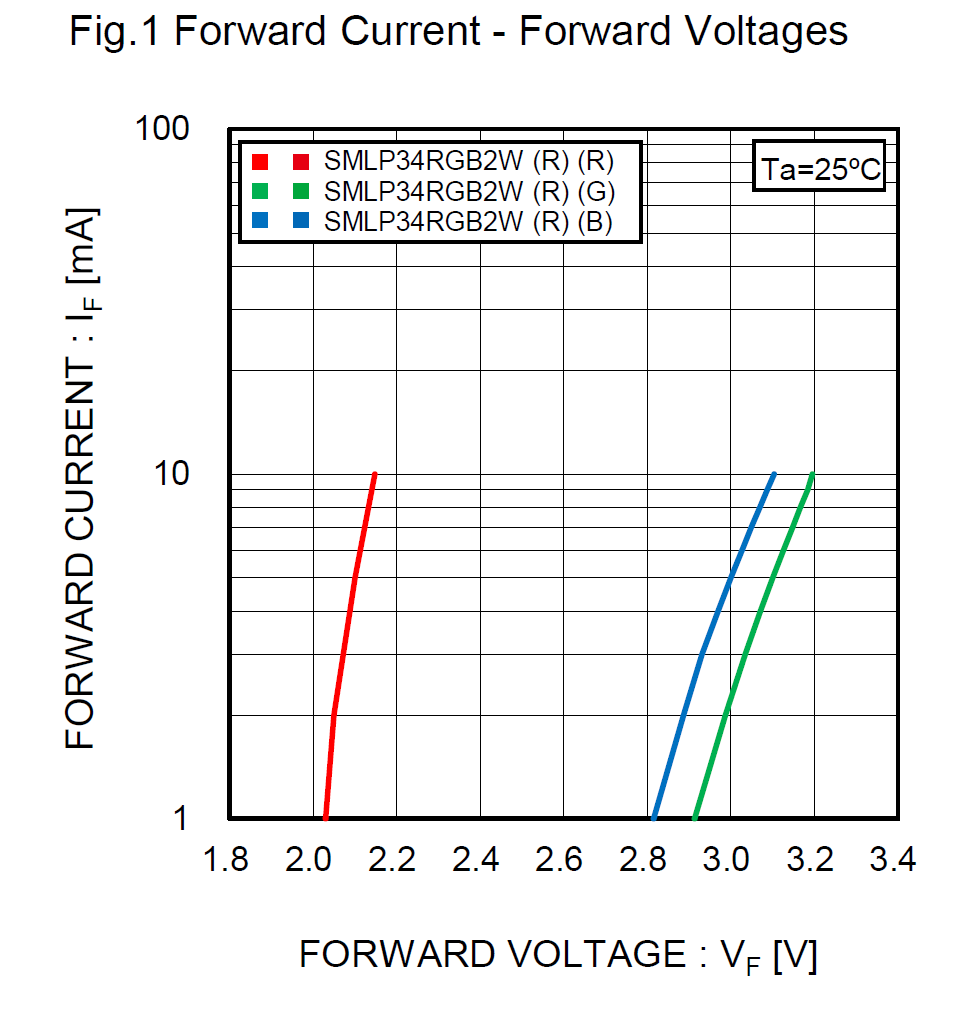
You really can't accurately predict the current in this sort of application. If you use the datasheet curves, you can guesstimate what it should be (roughly) but slight changes in supply voltage, in driver drop and changes in temperature (as well as part-to-part variations) will cause large changes in the current.
As you didn't grace us with a link to the part datasheet (assuming that a decent one even exists), I'll pull one at random (an Rohm SMLP36RGB2W3) off the interwebs and refer to it:

With this particular set of RGB LEDs, you can see that the RED LED is going to be easy. With a nominal 3V Vdd we can put zero ohms in series (leaving nothing for the driver) and the blue LED will conduct about 5mA. The green LED with zero ohms in series will typically only conduct about 2mA.
However if the supply voltage (with zero ohms in series) is increased or decreased, the blue LED will go from 1.5mA to more than the 10mA maximum. The green LED will go from way under 1mA (basically off) to more than 7mA. In this case, the green LED has a higher Vf than the blue, because its high-efficiency InGaN construction rather than the cheaper GaP.
If the green was GaP, it would probably be workable (over moderate temperature range and with a tightly regulated Vdd) but you're really in guessing (or at least empirical testing) territory rather than engineering territory. You certainly will not be able to get a stable "white" by combining RGB since the color balance will change radically with supply voltage and temperature.


Iffor the green and blue LEDs should be in the datasheet. \$\endgroup\$