20
\$\begingroup\$

Many circuit designs I see with transistors use two transistors chained together instead of just using one transistor. Case in point:
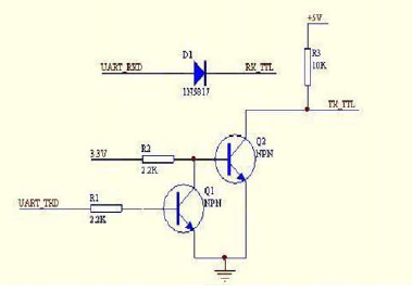
3.3V -> 5V signal amplifier

This circuit is designed to allow a device with a 3.3V UART to communicate with a 5V microcontroller.

I understand that when Q2 is off, TX_TTL will be high, and when Q2 is on, TX_TTL will be low. My question is, why not run UART_TXD directly to the base of Q2 instead of using Q1 to control the base voltage of Q2?

\$\endgroup\$
2
  • 9
    \$\begingroup\$ Using one transistor would invert the signal. Two transistors inverts it back again. \$\endgroup\$
    – pjc50
    Commented May 15, 2014 at 11:19
  • 1
    \$\begingroup\$ double transistor is not needed if using PNP, as logic level shift does not happen \$\endgroup\$
    – Lesto
    Commented May 15, 2014 at 16:19

2 Answers 2

23
\$\begingroup\$

What you have is basically a two stage amplifier - two consecutive amplifiers. In such a circuit configuration the gain of both amplifiers multiply. Since each stage has negative gain in your example, the overall gain is positive again.

So let's say Q1 and R2 have a voltage gain of -10 and Q2 together with R3 create a gain of -10, too. Then the overall gain is 100 which is positive and much larger than the gain of a single stage.

In your example this means the following: If UART_TXD goes High, TX_TTL will go High, too. If you omit Q1 and directly feed Q2 with UART_TXD, then TX_TTL will go Low when UART_TXD is High.

\$\endgroup\$
2
  • 4
    \$\begingroup\$ agreed - in the given digital circuit example gain is not important, only the signal inversion. Thats what the last paragraph of my answer says. Nonetheless the question is asked in a general way, no limitation to the digital domain. In analog circuitry you do cascade stages in order to boost the small signal gain. \$\endgroup\$
    – primax
    Commented May 15, 2014 at 11:50
  • \$\begingroup\$ Higher gain in a digital output stage would mean faster transitions, edges on waveforms more squared up, right? A single transistor would be "slower". Maybe it only matters if the gain is so low that it takes a significant percentage of the clock cycle for the signal to fully transition hi/lo or lo/hi? \$\endgroup\$
    – Matt B.
    Commented May 16, 2014 at 5:28
9
\$\begingroup\$

As noted by others, the main aim here is to achieve a non-inverting level converter.

For "extra points" you could use the circuit below.
The driver needs to be able to provide the output current (but not the voltage.)
As Iload_max =~ 5V/10k = 0.5 mA most input drive sources will be OK.

Vin = high = 3V3 -> Q1 off
Vout pulled high by R2.

Vin = low = ground -> Q1 on.
Vout pulled to Vin via Q1 CE on
I load = 5V/10k must be sunk by input drive.

This circuit is of special value when driving a high voltage load from eg a microcontroller. Vout max is set by the voltage rating of Q1.
The input drive pin must be able to sink the load current.

This is a "common base" amplifier 'drawn funny'.

schematic

simulate this circuit – Schematic created using CircuitLab

\$\endgroup\$
2
  • \$\begingroup\$ Interesting! Are there any advantages to using the two-transistor method (shown in my original question) over this configuration? I'm just wondering why the designer in the circuit I'm looking at would choose to use two transistors chained together instead of this configuration, which only requires one! \$\endgroup\$
    – Nate
    Commented May 15, 2014 at 14:57
  • 2
    \$\begingroup\$ @Nate - As I noted, the one transistor circuit requires the input driver to be able to sink the load current. In the case of logic level signals (such as here) this is seldom a problem. In the case of power loads the driver is usually unable to sink enough current. | The other reason to not use it is it is unusual and people cannot see how it works and it tends to cause brains to explode (it doesn't take much in some cases) and the zombies get grumpy. \$\endgroup\$
    – Russell McMahon
    Commented May 16, 2014 at 13:44

Your Answer

By clicking “Post Your Answer”, you agree to our terms of service and acknowledge you have read our privacy policy.

Not the answer you're looking for? Browse other questions tagged or ask your own question.