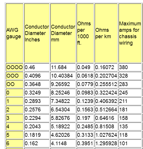
The problem with light jumper cables is not typically the ampacity of the wire, it's the voltage drop due to the resistance. Two AWG 10 wires will handle similar current to a single AWG (110A vs. 101A) as can be seen from the table I've linked. The reason is that there is more surface area on two wires so they can shed the heat better.
That does not help your car to start because it means that the power that should be cranking your engine smartly is going into the wires and not the starter motor.
So you want to keep the resistance down to the equivalent of AWG 6 for 7', which is 2*7/1000 * 395m\$\Omega\$ = 5.53m\$\Omega\$ (using the ohms/1000' values from the table I linked- image below). Three strands of AWG 10 are 2 * 7/1000 * (1/3) * 1000m\$\Omega\$ = 4.67m\$\Omega\$, which is a bit better.
If you make the cable longer, you would want to keep the total loop resistance similar, so an even heavier gauge of wire is called for. It's not uncommon for 16' jumper cables to be AWG 4, but that works out to 6.3m\$\Omega\$, which is worse than your three strands of AWG 10 that are only 7' per side.

Edit:-
The question has been raised that perhaps the ratios of ampacity for chassis wiring do not represent the ratios of ampacity for free air, that they might somehow be completely different rather than roughly 2:1 for free air. I won't insert the relevant charts here, because to use them you have to refer to a lot of other charts and derate for various factors (and they are not conservative without derating), but to pick a single data point, continuous operation at 70°C rise (limited by insulation rating), the AW6 ampacity is 120A and AWG 10 is good for 60A, so just as I said. Derating for bundling the AWG 10s into triples or doubles is left as an exercise for the reader, since ampacity is really the wrong thing to be looking at, once we have established that it is more than adequate. Refer to FAA specification 43.13-1B for more information.

