10
\$\begingroup\$

I have a 6.5" x 4.5" double sided board that is mixed analog and digital.

I have partitioned the analog and digital grounds from each other and have zero ohm resistors that bridge the two grounds together.

But my layout involves a lot of vias. When I looked at the drill output file, its about ~400 vias. The bottom traces are kept as short as possible so as to just allow routing on the top layer, but because of that, I have a lot of vias.

Is this common to have so many vias? Should I look to make longer traces to reduce via count?

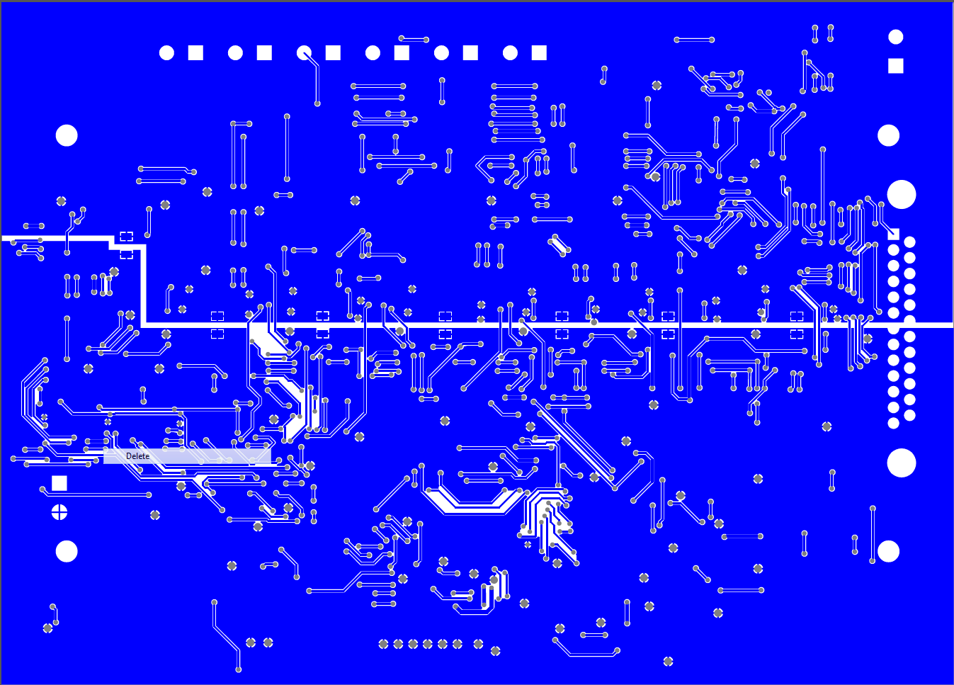
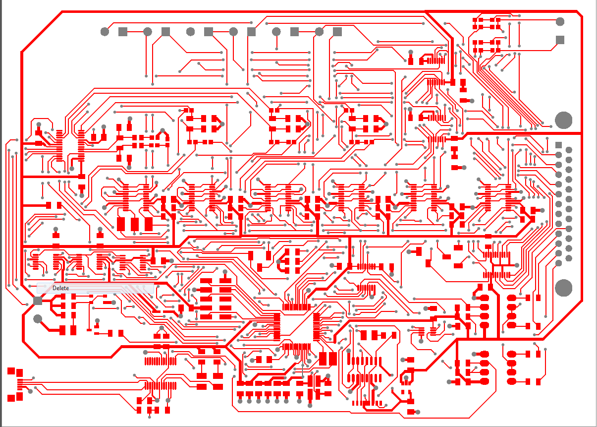
Update Added top and bottom layers

top

bottom

\$\endgroup\$
11
  • 2
    \$\begingroup\$ What are the vias doing? A lot of stitching of pours and such like or are there a lot of traces that pass through many vias to get from A to B? How dense is this board? How short are the AVdd/DVdd/AGND/DGND traces? You have multiple points tying the grounds? I hope it's better than it sounds. Did you consider 4-layer? \$\endgroup\$ Commented Jun 15, 2014 at 22:14
  • \$\begingroup\$ @SpehroPefhany they pass signals from A to B. It's mainly to pass to jump below a top level trace. \$\endgroup\$
    – efox29
    Commented Jun 15, 2014 at 22:20
  • \$\begingroup\$ If your power and ground lines and the current flow through them look good, then all is probably okay. I've had dense boards with that many vias in less area. But if your grounds and power lines are serpentine, then reducing vias won't help. Precision analog, USB differential data lines, Ethernet, LVDS etc. require some care, of course. \$\endgroup\$ Commented Jun 15, 2014 at 22:23
  • 1
    \$\begingroup\$ @SpehroPefhany I routed power first. They dont travel through vias. This is my first analog board - very scary stuff. With everything you read, its intimidating. \$\endgroup\$
    – efox29
    Commented Jun 15, 2014 at 22:29
  • \$\begingroup\$ "and have zero ohm resistors that bridge the two grounds" - I'd be inclined to replace them with ferrite beads... \$\endgroup\$
    – Majenko
    Commented Jun 15, 2014 at 22:39

3 Answers 3

10
\$\begingroup\$

For basic low frequency work vias are pretty much "meh". The only thing you need to watch for is when running larger currents - the vias tend to have a higher resistance, so dissipate more heat.

However, the interesting things start happening at higher frequencies.

Vias start to become antennae. They can radiate EMI like nobody's business. So for high frequency signals, keep the vias to a minimum.

And by "high frequency signals" I don't just mean if you're intentionally working on RF systems. Digital systems have some very high frequency components too. For instance, a 10MHz SPI bus - the clock is running at 10MHz, with harmonics at 30MHz, 50MHz, 70MHz etc (depending on slew rate of course).

Also you have the question of impedance to look at. A via has a different impedance than a normal trace, so if your circuit is impedance sensitive (if you are doing impedance matched traces, PCB antennae, etc) then you have to take the vias into account in your calculations.

So for general power distribution, vias should be noted and thought about. For high frequencies, vias are anything from frowned upon to down right no-nos.

Everything in between is pretty much irrelevant.
\$\endgroup\$
1
  • \$\begingroup\$ thats good to hear! I do have an SPI bus, but I can clock it to 1Mhz or so and not its full rated speed. Everything else is very slow frequency. It's basically a bunch of delta-sigma ADCs with very low sampling and some digital pots. I'm basically just reading the resistance. And the current through this board is kept on the low side. \$\endgroup\$
    – efox29
    Commented Jun 15, 2014 at 22:27
6
\$\begingroup\$

One thing to be aware of is that when you're doing very large scale production, or optimizing heavily for cost vias do increase board cost marginally.

The more vias, the more time your board has to spend in the drilling CNC.

\$\endgroup\$
5
\$\begingroup\$

For a two sided board the ground plane is best kept as intact as possible and if this means via count goes up then so be it. This is a generalism so it can change depending on the type of circuit. Having said that, 400 vias seems a lot.

EDIT due to OP showing pictures.

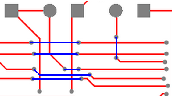
I see the artwork you've done but there is a lot more you can do to minimize the impact on the ground layer. Look at the following small section I copied: -

enter image description here

If the three vertical red traces (left of diagram) were routed closer to each other, the blue tracks that break the ground plane would be miniscule in comparison. You've got to try harder in to minimize the discontinuities in the ground. The vertical blue track could possibly stay as a red track and sneak around the two red traces it crosses. There are lots of examples on your PCB where improvements can be made and yes, don't worry too much about via count - EMI performance is more important.

\$\endgroup\$
3
  • \$\begingroup\$ That's what i thought as well, to keep the ground plane as solid as possible, and the count does seem high. I've never used so many vias before but at the same time, I've never done mixed analog before either. I look at my board and it looks like its been riddled with bullets lol. Maybe I should take some longer routes then ? - that might reduce my count. \$\endgroup\$
    – efox29
    Commented Jun 15, 2014 at 22:15
  • 2
    \$\begingroup\$ @efox29 Maybe post a picture of the layout? \$\endgroup\$
    – Andy aka
    Commented Jun 16, 2014 at 7:46
  • \$\begingroup\$ You're right, some work could have been made in that area and possibly others. I'll have to plan and come up with a better approach to layout and review and budget time for it. Unfortunately, the boards already went out. I'll find out in a few days if I got lucky or not, and if not, lessons to remember. Appreciate your advice. \$\endgroup\$
    – efox29
    Commented Jun 19, 2014 at 5:27

Your Answer

By clicking “Post Your Answer”, you agree to our terms of service and acknowledge you have read our privacy policy.

Not the answer you're looking for? Browse other questions tagged or ask your own question.