3
\$\begingroup\$

I am designing a prototype 5VDC fan speed control unit. I am using an LM317 as a voltage regulator. This will step the voltage from a LiPo battery or arbitrary wall adapter down to 5V. Pulse width modulation is used for actually controlling the fan speed.

As an alternative means of powering the device, I have been asked to install a female USB port which will interface with a solar powered USB charger being developed by a third party. I was hesitant to install the USB port for several reasons. The first is that the fan can draw about half an amp, much more than most USB ports can safely supply, so if it were plugged into a computer, for example, frying electronics is a possibility. The second is that I have no way of isolating the jack/battery power supply from the USB power supply and if both are connected at the same time, the results could be bad.

I was assured that this is a demonstration and testing prototype only, not a manufacturing prototype, so care will be taken not to misuse the USB port. Now my problem is that I don't want to run the 5V USB supply through the LM317, since the LM317 requires a voltage drop across its input and output pins to function properly.

My questions are:

  1. What would happen if I connected the 5V USB in parallel with the output of the LM317 voltage regulator circuit?
  2. What happens when I supply a voltage to the output and leave the input an open circuit?
  3. Also, does this potentially solve or mitigate the dangers of erroneously connecting both jack/battery and USB power supplies simultaneously?

I have inserted the proposed schematic here.
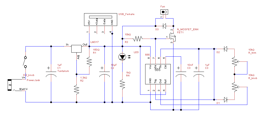
Schematic

\$\endgroup\$
5
  • \$\begingroup\$ related: electronics.stackexchange.com/questions/57209/… \$\endgroup\$ Commented Jun 17, 2014 at 0:37
  • \$\begingroup\$ If you read carefully, this isn't the same problem. \$\endgroup\$
    – Void Star
    Commented Jun 17, 2014 at 1:08
  • \$\begingroup\$ Why don't you just want to put the USB 5V before the regulator? That's a good practice since you don't know where the 5V is coming from on that USB connector. Its not like you'll be connecting the barrel jack and the USB at the same time...right? \$\endgroup\$
    – Funkyguy
    Commented Jun 17, 2014 at 3:21
  • 1
    \$\begingroup\$ The LM317 will cause there to be a voltage drop, am I not correct? If 5V goes in, I could end up with less, not much less, but still significantly less than 5V powering my fan. \$\endgroup\$
    – Void Star
    Commented Jun 17, 2014 at 4:38
  • \$\begingroup\$ You should take a look at the Arduino Uno schematics. That does exactly what you want - isolation of the two supplies from each other, zero loss on the USB, etc. \$\endgroup\$
    – Majenko
    Commented Jun 17, 2014 at 9:13

1 Answer 1

3
\$\begingroup\$

For a prototype, with careful use, this would still have problems. The LM317 does not tolerate reverse voltages, but you can protect it by putting a diode across it, allowing any reverse current to flow through the diode to the other side (just the capacitor in this case).

In no case should the external power and the USB be connected at the same time.

The USB port should be capable of supplying 500mA at 5V without a problem, so it would appear to meet your needs.

In a production circuit, if you can handle a little droop on USB voltage, use a diode from the USB connection to the circuit's 5V rail. If the USB is connected and no external adaptor is connected, then the USB will supply up to 5V (after the diode's voltage drop). If the external adaptor is connected and not USB, then the external adaptor will supply all the required current at 5V. If both are connected, the external adaptor will be at 5V, while the USB will be lower, thus the diode will protect the computer from possible issues, and the USB won't supply any current.

It's not the best design, but it's quick, simple, cheap, and will save others from damaging their USB ports. There are many ways to handle this problem more elegantly, many using mosfets to switch the best available power into the circuit. But for a simple prototype, this isn't a bad start.

\$\endgroup\$
2
  • \$\begingroup\$ I'm having difficulty sourcing a good diode part. For the diode across the LM317, is a forward voltage drop of 1V sufficiently low? \$\endgroup\$
    – Void Star
    Commented Jun 18, 2014 at 8:05
  • 1
    \$\begingroup\$ It depends on the LM317 you have. The TI LM317 datasheet indicates Input-Output Voltage Differential +40V, −0.3V so a diode with a 0.3V drop or lower would be required. \$\endgroup\$
    – Adam Davis
    Commented Jun 18, 2014 at 11:46

Your Answer

By clicking “Post Your Answer”, you agree to our terms of service and acknowledge you have read our privacy policy.

Not the answer you're looking for? Browse other questions tagged or ask your own question.