1
\$\begingroup\$

I thought making this would be simple, but I've found it a lot harder than I anticipated! What I mean is that I have one screen/monitor, and two video players (all video is through RGB component, RCA cables). What I need is a system to be able to switch which of the two devices is connected to the monitor, and thus has it's signal displayed.

I am aware that numerous devices such as this exist already, however I require one that can be operated wirelessly from a RF remote (since the signal has to travel through a wall). To be clear I don't mean that the video signal itself travels wirelessly, I just mean I can change the state of the switch remotely.

My current plan is to use a "wireless relay" which I found on eBay, but I'm not quite sure how these devices work, and most of the documentation for them is in Chinese so it doesn't make life easy... Here is a photo of what I'm talking about: "Wireless Relay"
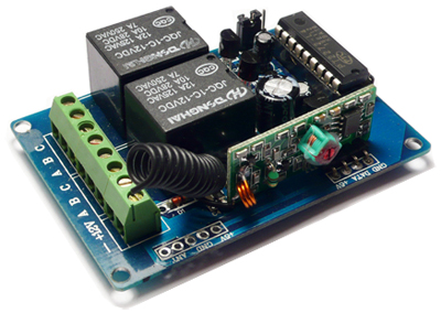
I'm worried that these things don't actually join a circuit, they just supply power to it when it receives a signal.

Additionally, since my video is in RGB format, (therefore it has 3 cables: Red Green and Blue) I was concerned that I would need a relay with 6 inputs, (while the one pictured only has 2). However I came up with a scheme which I think will allow me to use the two input relay, but I'm not sure... Here's a diagram of it (assuming a relay works the way I think it does) enter image description here
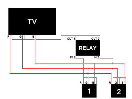
So in one state the relay will only have IN1 connected to OUT1, and in the other state the relay will connect IN2 to OUT2, whilst closing IN1 and OUT1. I dunno... will this work or am I crazy?

\$\endgroup\$
3
  • \$\begingroup\$ Relays are mechanical switches, just like your the one on your wall that controls your lights. You essentially have Mains Power and GND where one is connected to the output at any given time. It looks to me that your schematic has the three RGB lines connected together feeding a single input on the relay. Unless you are simplifying the schematic, this will not work unless the relay switches multiple input lines (which from the OP it appears this is not the case). Perhaps I too am novice in this space, but I would think you'd otherwise need 3 relays per RGB lines that synchronously switch. \$\endgroup\$
    – sherrellbc
    Commented Jun 20, 2014 at 6:21
  • \$\begingroup\$ @sherrellbc Your right that three lines connect to one input, however these grey lines represent the negative part of the RCA cable, note each output/input in the devices has two terminals (red and grey) per R/G/B, representing the positive and negative components of these cables. I thought negative can be combined since A/V 3.5mm cables do it no problem. \$\endgroup\$
    – protango
    Commented Jun 20, 2014 at 6:33
  • \$\begingroup\$ Don't disconnect the ground and leave the signal connected. You will have 2 problems: 1. noise from a "ground loop" as the ground finds another high resistance path back, and 2. the two signals will interfere with each other. \$\endgroup\$
    – Majenko
    Commented Jun 20, 2014 at 9:48

1 Answer 1

1
\$\begingroup\$

You are right in thinking you can use relays. However, you are wrong in thinking you can switch just the ground and leave the signal connected.

The shield round the RCA cable is only one of the ground routes between the TV and the video source. They are also connected via the mains cables, unless you're running from batteries. With the ground disconnected as you were envisaging, the signal would return to the video source through another route, one which is very noisy, high impedance, and just generally messy. So your signal would still be there, but massively corrupted.

Secondly, as that signal will still be there, so will the other signal, so you will have both signals there all the time fighting with each other.

A relay, as commented, is a mechanical switch. It is an electromagnet that moves a chunk of metal (armature) and forces it against one of two metal plates (contacts). The "common" connection is linked to the armature, and the "NC" and "NO", or "Normally Closed" and "Normally Open" pins are connected to the two contacts. A spring returns the armature to the "NC" position when power is removed from the coil.

So, with 3 relays, you can have 2 groups of 3 signals switched. The TV end goes to each of the common pins, and the incoming video signals go to the NC and NO pins, one for each video (make sure you keep them the same for all the video signals ;) )

As you only have 2 relays that is a little tricky. I can tell you now that it isn't possible to switch 3 signals with 2 switches. So you need to add a third relay. You could either buy 2 boards and control them individually, or you could get 2 more extra relays that run from the same power and use one of the on-board relays to switch the other two relays. Or to simplify, those two extra relays could be one single "double pole" relay - a relay that is like having 2 relays in one box with one coil - it switches 2 signals at once.

\$\endgroup\$

Your Answer

By clicking “Post Your Answer”, you agree to our terms of service and acknowledge you have read our privacy policy.

Not the answer you're looking for? Browse other questions tagged or ask your own question.