1
\$\begingroup\$

Am really a noob in this regards, therefore, need help to build an easy 12V circuit which when circuit "A" is powered off enables "B" circuit to switch off for 2-3 seconds and then turns on. Hopw I have clarified myself, I have searched it but not found the answer. Would really appreciate the help.

Thanks so much everyone for the prompt suggestions, will get the material and build both the circuits tomorrow and will let you know the results. It is a required for cluster of my vehicle and circuit 'B' is basically always open circuit as it supplies power to retain clock/date memory in the cluster. Here I will add that if this circuit 'B' is disconnected for longer duration the memory of clock/date is reset. As far as circuit 'A' is concerned it is basically the ignition switch and when it is ON nothng is required to be done to circuit 'B', however, when 'A' is switched OFF then 'B' has to be disconnected for 2-3 seconds and then connected again to overcome a problem of the dials illumination (i.e the power remains ON in the cluster when the vehicle is switched OFF if not cutoff). Hope I have clarified myself :)

\$\endgroup\$
6
  • 1
    \$\begingroup\$ First, how much current do A and B require? And am I correct that you want B to turn off for 2 or 3 seconds, and then turn back on? Do you care what happens to B when A turns on? \$\endgroup\$ Commented Jun 22, 2014 at 15:15
  • 1
    \$\begingroup\$ Can you describe your application? \$\endgroup\$
    – EM Fields
    Commented Jun 22, 2014 at 15:38
  • \$\begingroup\$ Seem the title of your question is difference than the text. \$\endgroup\$
    – Roh
    Commented Jun 22, 2014 at 16:38
  • \$\begingroup\$ @Roh, agree, I switched it. \$\endgroup\$
    – tcrosley
    Commented Jun 22, 2014 at 17:53
  • \$\begingroup\$ Two Schmitt inverters A & B in series. Vin couples to A input with cap. Resistor to high from A input. Done | Vin low pulls Ain low so Aout high = Bin high so Bout low = Vout. R charges cap after t =RC. Set RC to suit. Diode across R, cathode to high resets cct rapidly. \$\endgroup\$
    – Russell McMahon
    Commented Jun 23, 2014 at 0:00

2 Answers 2

1
\$\begingroup\$

The following circuit should accomplish what you want:

Normally pin 3 of the 555 timer is off, which keeps the P-channel MOSFET Q1 (high side switch) on, which powers circuit B (output on the left).

When circuit A (input on the left) is powered off, the line going into the trigger input (pin 2) of the 555 is monetarily brought low (C1 and R1 act as a differentiator) and triggers the 555 configured as a monostable. The output pin 3 goes high for 2.5 seconds (determined by the combination of R1 and C2), then pin 3 goes back to 0, turning the MOSFET back on.

The MOSFET is rated at 5A. If for some reason you can't drive circuit B from the MOSFET directly, a lower-amperage MOSFET could be used to operate a relay. enter image description here

\$\endgroup\$
5
  • \$\begingroup\$ I think we can find an approach easier than your answer.(also I up-voted your question for quick and good answer like always.) \$\endgroup\$
    – Roh
    Commented Jun 22, 2014 at 18:20
  • \$\begingroup\$ @tcrosley: The 555 needs a low-going pulse to 1/3 Vcc on the TRI input for a period shorter than the output pulse, so your circuit won't work if A stays OFF, or low, for longer than about 1.1 R1C2. You can fix it by disconnecting R2 from GND and connecting it to Vcc, and by differentiating the low-going edge of A with C1 replacing the wire between the junction of A and R2, and TRI. \$\endgroup\$
    – EM Fields
    Commented Jun 22, 2014 at 19:22
  • \$\begingroup\$ @tcrosley: Oops... If A goes open-circuit OFF, then the 555 will never trigger because there'll be nothing there to pull TRI down. There's a simpler way using a comparator, I think, and I'll post an answer in a while, if someone doesn't beat me to it. ;) \$\endgroup\$
    – EM Fields
    Commented Jun 22, 2014 at 20:42
  • \$\begingroup\$ @EMFields The fourth paragraph of page 5 of this datasheet supports your earlier comment that the trigger input should not remain low. Therefore I have added your suggested modifications to the circuit. Thanks. \$\endgroup\$
    – tcrosley
    Commented Jun 22, 2014 at 21:16
  • \$\begingroup\$ Thanks and I have edited my post for the clarifications please. \$\endgroup\$
    – tjkhattak
    Commented Jun 23, 2014 at 13:39
0
\$\begingroup\$

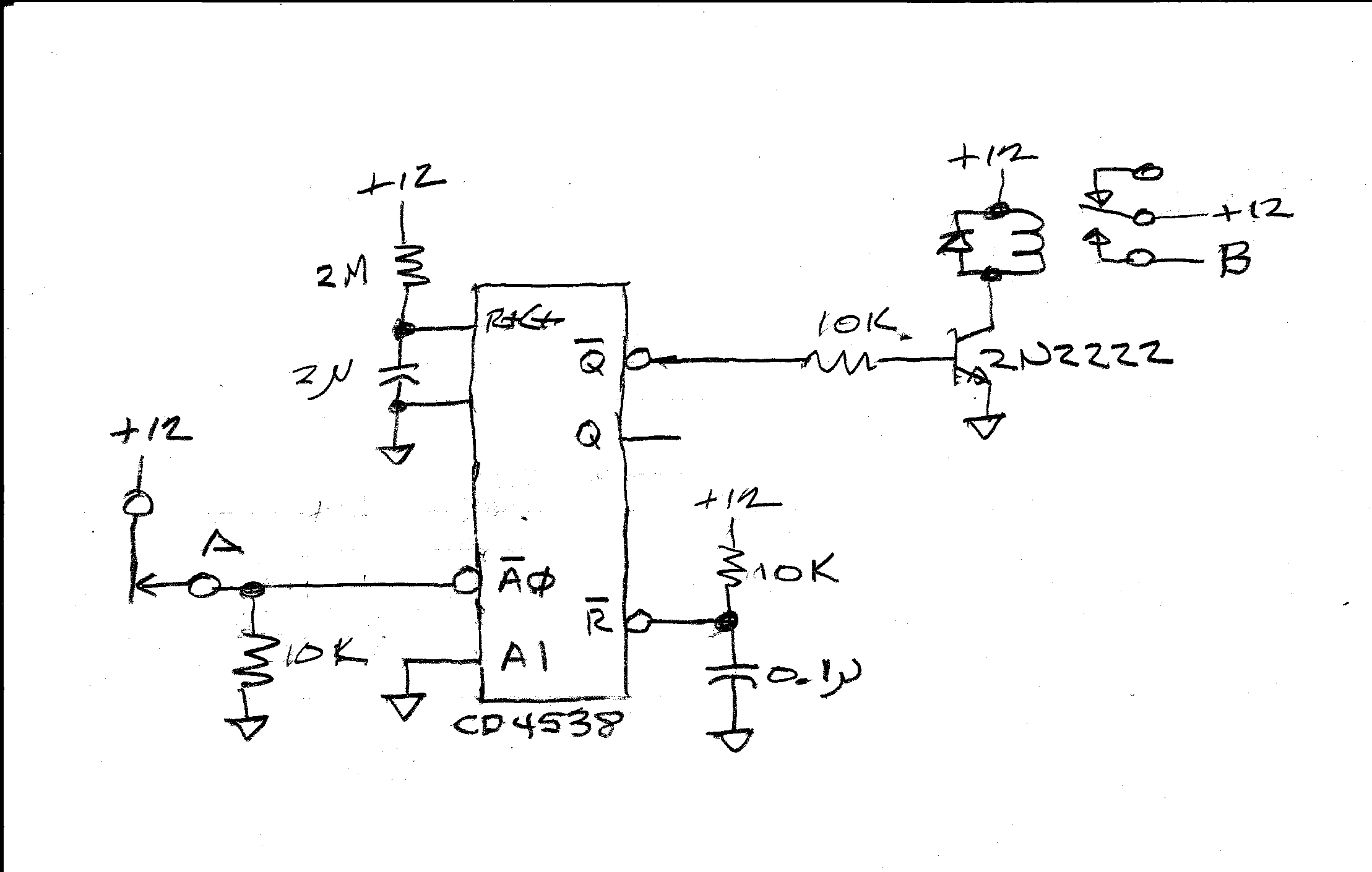
The 4538 is a pair of level as opposed to edge sensitive monostables, and has Schmitt trigger inputs, so no matter whether "A" is a totem pole or an open circuit input, when the switch at "A" opens, A\0 will be taken low and a low-going output pulse will occur at Q\, turning off the 2N2222 and de-energizing the relay for the duration of the output pulse.

enter image description here

\$\endgroup\$
1
  • \$\begingroup\$ Thanks will try this also and let you know of the results please. \$\endgroup\$
    – tjkhattak
    Commented Jun 23, 2014 at 13:36

Your Answer

By clicking “Post Your Answer”, you agree to our terms of service and acknowledge you have read our privacy policy.

Not the answer you're looking for? Browse other questions tagged or ask your own question.