I have built an EEG amplifier with gain of 2000 and bandwith at 1~40Hz.
I use an Instrument Amplifier for pre-Amp and a non-inverting opamp as post-amp and finally bandlimit at 40Hz using a 4th-order LPF.
I would like to measure the SNR for my EEG amplifier but I do not know the proper set up and therefore I come out with the following experiment steps and please verify for me am I doing the right thing.
How I record the measurement: I connect the analog output to the SADC pin of ARM MCU. The ADC sampling rate is 7000 samples per second
My input: A differential Sine wave from function generator @ 10Hz
My output: An amplified Sine wave @ 10Hz @ gain = 2000
1. Measure the Vrms for noise
1.1 Let input of INA to open and then power on the amplifier.
1.2 Measure the output and record the ADC data
1.3 I record the output for ~5 seconds which give me ~50,000 data
1.4 I select a portion of 10,000 continuous data sample, which is 1-10001 data samples
1.5 Calculate the Vrsm using similar equation provided here
1.5.1 Calculate the power of 2 for each of the 10, 000 data
1.5.2 Calculate the average result of the total data (which is divided by 10000)
1.5.3 Vrms = Square root the result of average of 10, 000 data
2. Measure the Vrms for signal
2.1 Let the input connect to a differential Sine wave generator
Repeat 1.2, 1.3, 1.4. 1.5 to calculate the Vrms of signal.
3. Calculate the SNR (db)
SNR(db) = 20 log (Vrms, signal / Vrms, noise);
My question: Am I doing the right thing for the SNR measurement?
Edit: Update question
Now I am confused. The MCU is powered at 5V from an eval board whereas my system is a 3.3V powered. The MCU SADC is taking the voltage measurement at pin SADC with reference to 0V (GND).
However, my system AGND is at 1.65V.
Therefore, how should I connect the output of my system to the eval board?
I try the following scenarios:
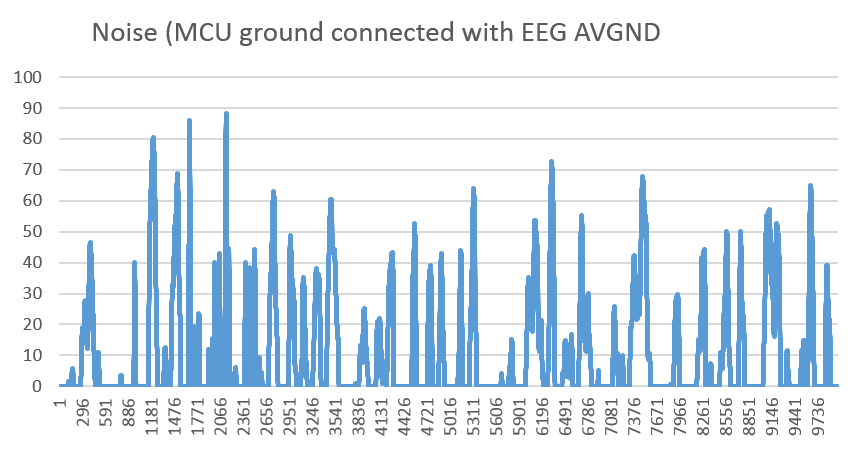
1. Connect the SADC pin to my EEG amplifier output and connect the MCU GND to my EEG AVGND
It will measure the noise like this, which is a sharp peaks:

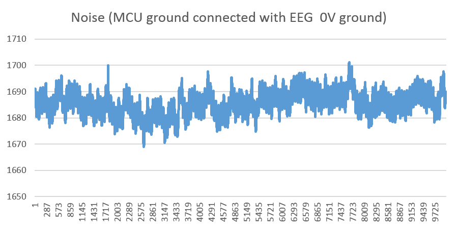
2. Connect the SADC pin to my EEG amplifier output and connect the MCU GND to my EEG 0V ground
It will measure the noise like this, which is looks like a power noise:

Which is the correct one? or both wrong?


G=2000is not enough for practical. But in my experiment, I am simulating a 200uV Vpp Sine input and give me a 400mV Vpp Sine output. In practical, I increase the gain to 8000 and it gives me a ~600mV peak for eye blink. I got use RLD. @Scott seidman Yes. It is working. I am still considering the DC restoration feedback. Is it real useful? What does it mean by leave enough headroom for 150mV electrode junction potentials? \$\endgroup\$