6
\$\begingroup\$

Ok, so I need to generate 50 V from 5 V, with a load of 0 to 20 mA, for a mass-produced device. There are simple boost converter circuits like this LT3467 example:
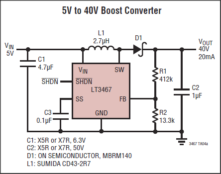
5 V to 50 V boost converter

but it seems these are limited by the maximum voltage on SW (in this case 42 V). Are there any that can go directly to 50 V?

If not, there seem to be several possibilities:

  1. external FET with higher voltage rating
  2. charge pump after the boost converter
  3. autotransformer instead of inductor

1: Is adding an external FET sufficient to get up this high? It seems like it, though I don't know how much current this can supply:
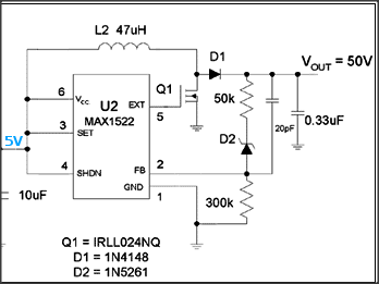
5 V to 50 V converter with external FET

(from here)

2: Can also use a charge pump / voltage doubler after the boost converter, without an external FET, something like this (with the FET built into the boost converter IC):
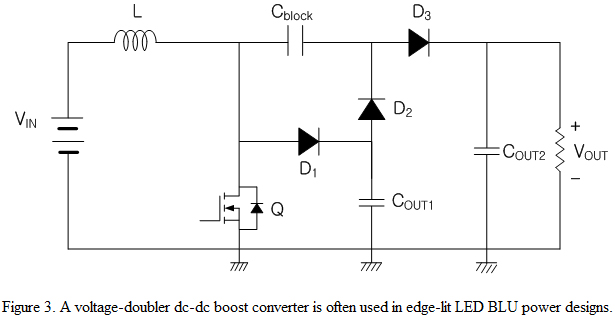
voltage-doubler boost converter

(from here)

Then the SW voltage can be half (or less) of the output voltage. One advantage of this is that it produces intermediate voltages, which might be useful. In this case, should the feedback be before or after the voltage doubler?

3: Other examples show an autotransformer replacing the inductor, and no external FET:
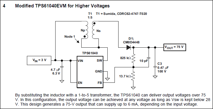
3V to 75 V converter with autotransformer

(from here)

(more here)

So, uh, what's the simplest/cheapest/best way to do this? What are the advantages and disadvantages of each solution? Which external components cost the most? Which solution can supply the highest current? Which has the best output regulation?

\$\endgroup\$
2
  • \$\begingroup\$ Is the switched capacitor output really +10V and not -10V? It looks to me that you have to reverse the direction of the D3 diodes to get +10V. \$\endgroup\$
    – jpc
    Commented Mar 24, 2011 at 0:53
  • \$\begingroup\$ @jpc: Yeah, not the first time I've seen an error in Maxim's schematics. :) I will try to draw what I actually mean instead of using their example. \$\endgroup\$
    – endolith
    Commented Mar 24, 2011 at 19:06

3 Answers 3

3
\$\begingroup\$

The best solution, but not the easiest, is to use a flyback converter topology. This will give you the most current, good efficiency, and the least issues. Other solutions, like a typical boost topology in your first two diagrams can work, but you have to watch out for any duty-cycle limitations on the converter chip.

Switched capacitor converters can work for currents of 20 mA, but are noisy and don't regulate well with a 10:1 increase in voltage. I've seen these used for generating +48v in commercial products, but I wouldn't recommend them.

\$\endgroup\$
2
  • \$\begingroup\$ What's the benefit of this over the autotransformer method? \$\endgroup\$
    – endolith
    Commented Mar 28, 2011 at 13:52
  • 1
    \$\begingroup\$ The autotransformer method is similar to a non-isolated flyback converter. When looking at chips you'll probably have better luck looking for the term flyback since it is more common than autotransformer. \$\endgroup\$
    – user3624
    Commented Mar 28, 2011 at 15:52
3
\$\begingroup\$

Try the Nat Semi Simple Switchers. Here are some examples I found with their interactive selection tool.

I used 5V to 6V input, 50V output and a current of 50 mA. You should be able to design a suitable circuit on-line that meets your cost and performance requirements.

\$\endgroup\$
0
\$\begingroup\$

From the ideas you provided I think the one with the external switch is the easiest. Obtaining or wiring your own flyback inductors is more difficult than just buying a medium-voltage MOSFET.

Just be sure that you use a chip with adequate output since an open drain output of a typical intergrated-switch DC/DC converter will not work with an external MOSFET.

I am not sure how you want to use the 10V switched capacitor circuit. All these are non-isolated circuits so you cannot just add the 10V to the 40V gnd-to-rail.

\$\endgroup\$
2
  • \$\begingroup\$ This is for mass production, not a one-off. For the capacitor circuit, I'd be generating 50 V, not 10. Running a boost converter that outputs 25 V at the SW pin, and then doubling it with two sets of diodes and capacitors. \$\endgroup\$
    – endolith
    Commented Mar 23, 2011 at 23:58
  • \$\begingroup\$ Sorry, I missed the point about mass-production. I dug further into the switched capacitor circuit and it looks really nice to me. \$\endgroup\$
    – jpc
    Commented Mar 24, 2011 at 0:51

Your Answer

By clicking “Post Your Answer”, you agree to our terms of service and acknowledge you have read our privacy policy.

Not the answer you're looking for? Browse other questions tagged or ask your own question.