4
\$\begingroup\$

I've been working on a model maglev train as my Grand Hobby Project; something around the H0 scale.

The initial idea was to use the Inductrack mechanism to keep it simple. To summarize, a Halbach array of rare earth magnets produces current in a conducting track, which in turn generates a repulsive force. Unfortunately the theory doesn't scale well downwards; either you have to go really fast (Mach 3) or need 3 cm of copper to drive the resistance down.

My current plan is to keep the array, but manage the currents in the track actively. Back-of-the-envelope calculations indicate I can get satisfactory lift with 2-3 amps, and I can even use PCB with 1 mm traces as the track without turning it into a hot plate.

However, that's still a respectable current where I come from, and the load is on the order of milliohms. I have no idea how to build a circuit that can drive those currents without blasting 99% of the energy in a sense resistor.

Other "requirements" are reproducibility and ease of setup. If I have to tweak a trimpot or solder 10 components for each trace in the track to get the forces to balance out, this thing will never get done. Optimal solution would be some off-the-shelf voltage-controlled IC.

\$\endgroup\$
1

3 Answers 3

2
\$\begingroup\$

So you can build a +/- 0.5V at several amperes power supply, using switching regulators, say.

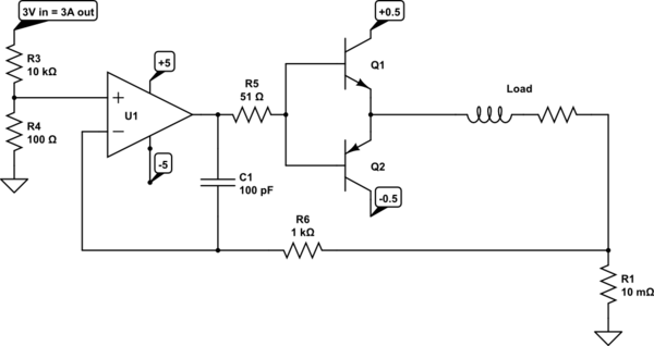
Then build an output buffer stage for an op-amp fed from that supply, current feedback from a small sense resistor (say 10-20m\$\Omega\$) with Kelvin connection. Done.

If you don't care about crossover distortion, a complementary pair of BJTs will do the trick. Since the op-amp will be powered by a much higher voltage (say +/-5V) there will be plenty of voltage to drive the bases.

Edit: Something like the below circuit. The transistors need to have a beta of something like 100 at your 2-3A, so the base current will +/-20-30mA. For example 2SB1412/2SD2118.

schematic

simulate this circuit – Schematic created using CircuitLab

As @GeorgeHerold suggests, if you only need one polarity, you can leave out the transistor and associated supply (probably the PNP would be best to excise), which makes it much simpler.

\$\endgroup\$
5
  • \$\begingroup\$ Unfortunately I've always found the BJTs a bit mysterious, so could you please provide a bit more details about the transistor solution? (Should have taken up the opportunity to learn in the university, but I only needed to pass the basic electronics course and knowing the op-amp was sufficient...) \$\endgroup\$
    – lrasinen
    Commented Jul 14, 2014 at 19:27
  • \$\begingroup\$ See edit above. You could use higher voltage for the supplies, (like +/-5v) but the transistors will get hotter (10x the dissipation) and would require heatsinks. \$\endgroup\$ Commented Jul 14, 2014 at 19:56
  • \$\begingroup\$ Looks like I could pull that off. One more thing(TM): What's the rationale for the R5 value? \$\endgroup\$
    – lrasinen
    Commented Jul 14, 2014 at 20:08
  • \$\begingroup\$ R5 is not too small wrt the medium frequency output impedance of most op-amps (usually around 100 ohms) and prevents oscillation via C1/R6. If you make it much higher, then it won't allow enough current to get to the bases, much lower and it won't perform the desired function. \$\endgroup\$ Commented Jul 14, 2014 at 20:31
  • \$\begingroup\$ Interesting choice of power transistors with low Vce(sat) implies Rce~ 1/16 Ohm with high hFE but is completely unnecessary with negative feedback reducing the driver impedance and the mag power is far too low with <1W \$\endgroup\$
    – D.A.S.
    Commented Dec 8, 2020 at 18:58
2
\$\begingroup\$

I think Spehro is talking about a push-pull output. A simple one is here. http://en.wikipedia.org/wiki/Push%E2%80%93pull_output

But I wonder if you need both polarities? If not then just an opamp current source with a transistor buffer. like fig 7 here, http://en.wikipedia.org/wiki/Current_source#Op-amp_current_sources

Should be fine...

\$\endgroup\$
5
  • \$\begingroup\$ Welcome, George! \$\endgroup\$ Commented Jul 14, 2014 at 20:05
  • \$\begingroup\$ The magnetic field is sinusoidal, so I'll need to match the direction of the current with the sign of the field. In the first prototype I plan to do this by physically routing the same current in $\phi$ and $\phi+\pi$ conductors, but in opposite directions. But when/if I scale this to full-track size, it might make more sense to have independent control of the currents for propulsion. \$\endgroup\$
    – lrasinen
    Commented Jul 14, 2014 at 20:16
  • \$\begingroup\$ Hmm so you will have loops of copper that match the period of the Halbach array, with a flip in the sign for each loop? \$\endgroup\$ Commented Jul 14, 2014 at 20:43
  • \$\begingroup\$ The protoboard will have just transverse copper strips matching the period which I'll connect with wires. Reason being that I can then use the same boards to test non-Halbach approaches. \$\endgroup\$
    – lrasinen
    Commented Jul 15, 2014 at 8:39
  • \$\begingroup\$ Did some back-of-the-envelope calculations: the system is the very definition of unstable. But that solves the propulsion question nicely; I can just plug a moving setpoint in the stability control. I also realized that an H-bridge can also handle the polarity issues, and I suspect that'll be cheaper than a separate supply for negative. But that's for prototype II, "Make it stay put". \$\endgroup\$
    – lrasinen
    Commented Jul 15, 2014 at 17:28
1
\$\begingroup\$

I'd go for a buck converter to give you low voltage high current with good efficiency. Then use a hall effect sensor to determine the current flow and use that as feedback to your buck converter to precisely control the current.

\$\endgroup\$

Your Answer

By clicking “Post Your Answer”, you agree to our terms of service and acknowledge you have read our privacy policy.

Not the answer you're looking for? Browse other questions tagged or ask your own question.