0
\$\begingroup\$

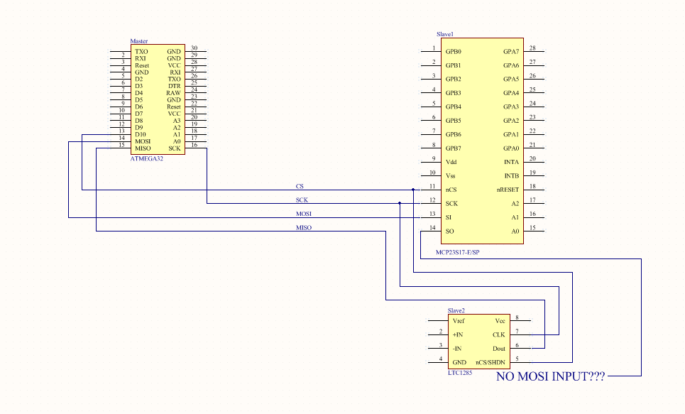
I need to connect 3 devices with SPI in a daisy chain configuration.1 master 2 slaves. the first slave is typically connected to the master: SCK-SCK MOSI-MOSI CS-CS The second slave on chain have no MOSI input, only SCK,MISO and CS. I can connect this slave device to the master (MISO) but I interrupt the chain beetween the two slaves. enter image description here The three device are: - Master: ATmega32 (MCU) http://www.atmel.com/images/doc2503.pdf - Slave 1: MCP23S17 (differential ADC) - Slave 2: LTC1285 (3V 12-bit A/D Converter) http://www.farnell.com/datasheets/1575635.pdf
Is it possible to connect theese 3 devices in a daisy chain configuration? Thanks for your help!

\$\endgroup\$
4
  • \$\begingroup\$ Linear Technology LTC1285 is not a 16-bit I/O expander, it's a 12-bit SAR ADC. cds.linear.com/docs/en/datasheet/lt1285.pdf. Why do you need to use daisy-chain configuration? Do you not have two available I/O pins to drive the MPC23S17.CS and LTC1258.nCS with separate chip-select signals? \$\endgroup\$
    – MarkU
    Commented Jul 22, 2014 at 9:45
  • \$\begingroup\$ Sorry that was an error posting: Slave 1: MCP23S17 (16-Bit I/O Expander) - Slave 2: LTC1285 (differential ADC) I can use only 4 pin for comunication, I know i could use others I/O pins for two separate communications but I can't. This because in my PCB I choose if comunicate with ATMEGA master or with one other out of the card..and I have only 4 free pin at mine disposal for communicate out of the card. \$\endgroup\$
    – Danny
    Commented Jul 22, 2014 at 9:53
  • \$\begingroup\$ And why not use LTC1288 instead of LTC1285, since you want an ADC that supports daisy-chained SPI? (Page 7 of LTC1285/LTC1288 data sheet. LTC1288 has DIN/MOSI and DOUT/MISO pins.) I realize they're not identical, but they share a data sheet so are probably the same silicon chip internally. \$\endgroup\$
    – MarkU
    Commented Jul 22, 2014 at 10:05
  • \$\begingroup\$ Yes. I see it. but I don't know if LTC1288 allows differential 1 signal measure. If you look on datasheet the input changes from In+ In- on LTC1285 to Ch1 Ch2 on LTC1288. Also on the pin description section (page 7) the description of theese two pins changes. Maybe is the same but it is not so well explained on datasheet. Do you think there are differences? \$\endgroup\$
    – Danny
    Commented Jul 22, 2014 at 10:23

1 Answer 1

2
\$\begingroup\$

You're misunderstanding how SPI works.

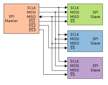
In an SPI bus every device connects to MISO, MOSI and SCK (or as many of those as there are on the chip) in parallel. Each device then has its own separate CS connection.

You drive one of the CS pins LOW and you can communicate with the device it is connected to. Drive that one HIGH, and the other one LOW, and you communicate with the other device. enter image description here

\$\endgroup\$
3
  • \$\begingroup\$ Thanks Majenko! SPI bus can be connected with 2 methods. ![enter image description here][1] [1]: i.sstatic.net/9QAaq.png I must connect it like in the second picture: daisy chain. Is it possible? I mean, my second slave has no MOSI input, only MISO... \$\endgroup\$
    – Danny
    Commented Jul 22, 2014 at 9:30
  • 1
    \$\begingroup\$ That is only possible with some devices that act as a shift register: electronics.stackexchange.com/questions/121430/… \$\endgroup\$
    – Majenko
    Commented Jul 22, 2014 at 9:43
  • \$\begingroup\$ is what I feared. This means that not all the devices using SPI can be connected on daisy chain..too bad! Thank you so much! \$\endgroup\$
    – Danny
    Commented Jul 22, 2014 at 9:56

Not the answer you're looking for? Browse other questions tagged or ask your own question.