0
\$\begingroup\$

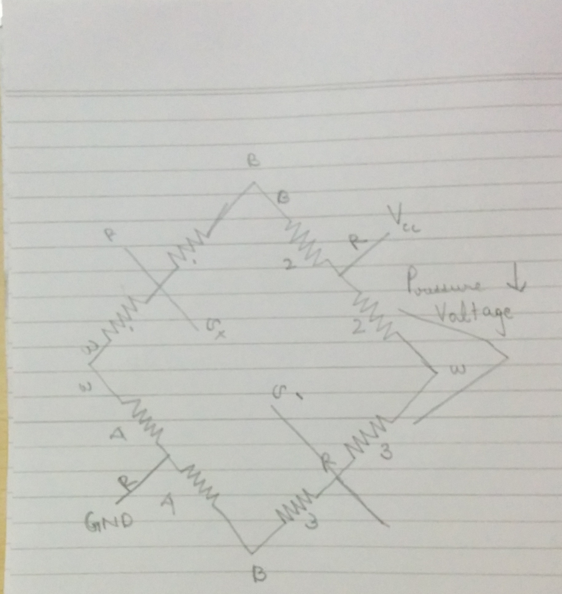
I am trying to get 4, 3 wire load cells connected together in the form of a wheatsone bridge correctly to measure weight. I have the following schematic used from this http://www.nerdkits.com/forum/thread/900/:

I am giving e+ 3V and e- to ground. I am measuring the difference between the S+ and S- terminal. When I put pressure on each of the load cells I see a deflection which goes postive for 2 cells and the voltage goes decreases(but not below 0 (stops at 0) ) when I put pressure on 2 other cells. When I place the load, the weight is uniformly distributed across all 4 cells and as a result the voltage is constant. But I know that this works because I tested it out before opening it up. What am I doing wrong and how exactly do I read these inputs from s+ and s- using an ad620 or LM307? enter image description here
\$\endgroup\$

1 Answer 1

1
\$\begingroup\$

When I put pressure on each of the load cells I see a deflection which goes positive for 2 cells and the voltage goes decreases(but not below 0 (stops at 0) ) when I put pressure on 2 other cells.

If you have scenarios where a weight over two of the load-cells increases voltage but the same weight over the other two decreases the voltage then you need to swap the two end wires of the two load cells that send the voltage negative.

how exactly do I read these inputs from s+ and s- using an ad620 or LM307?

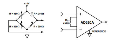
Use this circuit but you might need a negative voltage supply to make sure the AD620 input voltage common-mode range is not infringed - read the data sheet.

enter image description here

\$\endgroup\$
5
  • \$\begingroup\$ My load cell has a a red terminal which is between a black and a white terminal. Right now I have connected each of the black wires to the corresponding black wires as shown in the schematic. What do you mean when you say "swap the two end wires". Do you mean to say I have to reverse the 2 black wires \$\endgroup\$ Commented Jul 27, 2014 at 11:47
  • \$\begingroup\$ Two of the load cells are producing the wrong direction of voltage so you have to "reverse" those two cells. This is done by reversing the wires which are normally called the excitation wires. I have no idea what colour they are and if you don't then how could you wire it up? I can't tell from your circuit either because it is blurred beyond recognition \$\endgroup\$
    – Andy aka
    Commented Jul 27, 2014 at 11:51
  • \$\begingroup\$ I have uploaded a new picture and tried all the different combination of swapping things around. I still dont get a uniform increase on all load cells. Could you tell me which 2 wires to swap? \$\endgroup\$ Commented Jul 28, 2014 at 4:00
  • \$\begingroup\$ I found the issue. While assembling I had put the 2 load cells the other way around. \$\endgroup\$ Commented Jul 28, 2014 at 5:30
  • \$\begingroup\$ thats the same as wiring them the wrong way too. Please consider marking my answer as correct. \$\endgroup\$
    – Andy aka
    Commented Jul 28, 2014 at 7:57

Your Answer

By clicking “Post Your Answer”, you agree to our terms of service and acknowledge you have read our privacy policy.

Not the answer you're looking for? Browse other questions tagged or ask your own question.