2
\$\begingroup\$

So I am trying to created a current source that will be used to drain a battery at specific time intervals for a specified duration.
schematic

simulate this circuit – Schematic created using CircuitLab

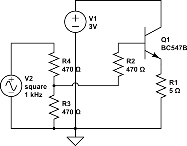
Here is the circuit that I am attempting to use, pulses from the square wave source will trigger the transistor allowing the current to flow and thus draining the battery.

This needs to be implemented three times for my design but the first two (which are 10uA and 10mA sources) work fine and do not vary much with changes in the battery voltage, however I am struggling a bit with my final current source which needs to draw 100mA+ from the battery. The issue is not with getting the correct current, but in fact getting the current to remain constant with changes in the battery voltage, that is the voltage at the collector of the transistor.

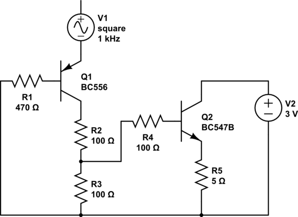
I was advised that I could possibly need a current buffer before the base pin of the transistor and I implemented this but it still does not yield a steady and constant current source! This is the circuit for the 'current buffer', not really sure what it is but that is what I was told to do:
schematic

simulate this circuit

As you can see all it is a pnp ahead of the previously show circuit. Again my issue is not with this, I just need a method of keeping the current very constant, ie. No significant change until the battery voltage has dropped < 1V or something like that!

Any help would be greatly appreciated!

\$\endgroup\$

3 Answers 3

2
\$\begingroup\$

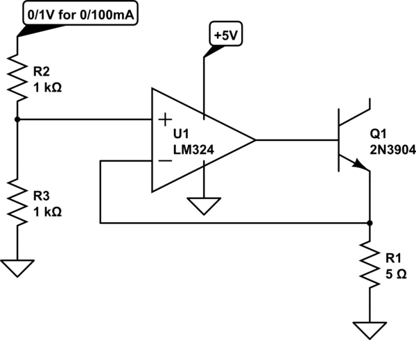
Try this:

schematic

simulate this circuit – Schematic created using CircuitLab

This circuit is capable of ~1% accuracy with good layout. If the battery is removed, the op-amp will current limit into the base, which should not hurt it. If you don't like that, or if you use another op-amp that doesn't current limit as well, add a small base resistor such as 100 ohms.

\$\endgroup\$
2
  • \$\begingroup\$ Hey, so I implemented this circuit and it works really well so thank you so much for that, but I was just wondering if you could provide a link with more theory behind this circuit so I can try to understand what is happening more and how I would go about calculating any values if I wanted to change the current! \$\endgroup\$
    – MrPhooky
    Commented Jul 31, 2014 at 8:50
  • \$\begingroup\$ If 1v is supplied for voltage divider, then voltage at noninverting terminal of op-amp = (1k/2k)*1V = 0.5V = 500mV ... Considering Ideal op-amp voltage at inverting terminal will also be 500mV ... Current passing through emitter resistor = 500mV/5 = 100mA \$\endgroup\$ Commented Mar 1, 2017 at 12:02
0
\$\begingroup\$

You have been getting some very bad advice.

First of all, your top circuit depends on the fact that the voltage across R1 needs to be constant, and for this to be possible, the base voltage of Q1 needs to be held constant. In other words, the base needs to be connected to a "stiff" voltage source — one with low source impedance. R2-R4 control the source impedance, and R2 is actually completely counterproductive here, since all it does is raise the source impedance.

In your second circuit, you have Q1 in a common-base configuration, which has no current gain at all, only voltage gain. This doesn't help at all. It does help slightly that R2-R4 have lower values, but R4 is still completely useless.

If you give us some actual performance numbers that you are trying to achieve, such as the nominal output current and the tolerance you can live with, we can offer better circuits.

\$\endgroup\$
0
\$\begingroup\$

Drwaring 100 mA from a battery at 1V requires that the load resistor takes much less than 1V I would aim for ~ 0.25 V, so I would lower the emitter resistor to ~ 2R2.

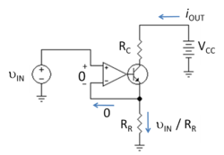
Your circuit has no overall feedback, I would suggest that you add an opamp. This circuit from http://en.wikipedia.org/wiki/Nullor is the classic. Divide your switching voltage down to 2R2 * 100 mA = 0.22 V before applying it to the + input of the opamp. You will need an opmap with an output range and common mode that includes ground, or use a negative supply. In any case you will need a separate supply for the opamp (not the battery).

enter image description here

PS the 100 Ohm bases resistors in your circuits should not be there: you are using the transistors as voltage followers (common collector), hence the impedance at the base is (very) high and hence such a resistor is generally useless

\$\endgroup\$
2
  • \$\begingroup\$ The voltage drop across the emitter resistor is the feedback, becasue it reduces Vbe across the transistor. \$\endgroup\$
    – Dave Tweed
    Commented Jul 30, 2014 at 13:39
  • \$\begingroup\$ Correct, but it does not include Vbe in the loop, which for the rather low voltage across the resistor might be a problem here. (I changed the wording a bit, added 'overall') \$\endgroup\$ Commented Jul 30, 2014 at 13:49

Your Answer

By clicking “Post Your Answer”, you agree to our terms of service and acknowledge you have read our privacy policy.

Not the answer you're looking for? Browse other questions tagged or ask your own question.