16
\$\begingroup\$

Fantasized in some of the survivalist, post-catastrophic novels, movies or docudramas is the radio built only with handcrafted or scraped components.

Beyond the popular appeal of this stories, I think there is a core of truth and passive elements are easier to scrap and handcraft, can easily be read and calculalted without a multi-meter or can be easily reused. Resistors/condensers can be put in series or in parallel. Coils can be uncoiled and re-coiled from transformers other coils etc.

Is it possible to build a very minimalist radio transmitter that can be built only with passive components, what would be the schematics for that?

\$\endgroup\$
3
  • 3
    \$\begingroup\$ Yes, it is possible to make a primitive transmitter without transistors or vacuum tubes. Look-up spark gap transmitter (like this one). It wouldn't be able to transmit voice (obviously), but it can transmit Morse code. \$\endgroup\$ Commented Aug 4, 2014 at 18:14
  • 3
    \$\begingroup\$ Rolled back to the original, as the context shows that the term "passive components" (ie, without gain) may not be the true criteria. \$\endgroup\$ Commented Aug 4, 2014 at 18:23
  • \$\begingroup\$ Of course somebody will need to have the corresponding receiver, or your transmitter isn't worth much to you... and in a survival world, do you want to advertise your existence to the other survivors clever enough to pick up your signal? They might come and raid you for resources... Still - interesting question. \$\endgroup\$
    – Floris
    Commented Aug 5, 2014 at 16:09

10 Answers 10

12
\$\begingroup\$

Is it possible to build a very minimalist radio transmitter that can be built only with passive components, what would be the schematics for that?

Sure. You can switch transients into a resonant circuit, as others have mentioned. The trouble here is that you end also transmitting a lot of those transients, which means a lot of broad-band noise. There's also the trouble that spark-gap transmitters are not permitted by international treaty. (Not that regulations matter much in a hypothetical post-catastrophic scenario, unless it's the authoritarian regime with a special emphasis on radio regulation variety)

Interestingly, one can make a CW transmitter (that is, one that transmits just one frequency, without the broadband noise) with passive components. All you need is a high frequency voltage source, which can be generated electromechanically.

For a real, working example, see the Varberg radio station. It is, quite simply, an AC motor, coupled to a generator to a 1:3 speed-increasing transmission, with the generator having 976 poles. The generator spins at about 2133 RPM (35.55 revolutions per second), and with 976 poles that makes at output at \$ 35.55 \cdot 976 / 2 = 17.35\:\mathrm{kHz} \$. The generator's output is switched into an antenna to transmit a tone, or into a short for the space between the dits and dahs. There's a bit of additional stuff to provide a matching network and control the motor, but it's all passive.

As for the premise of the question, that passives are easier to scrap, that may be somewhat true. However, discrete active components, like transistors, are not so hard to scrap either. Certainly, easier than building an electromechanical transmitter. A transistor radio can run off batteries, is more portable, and energy efficient. So in most ways that I imagine a post-catastrophic world, I would probably end up with a transistor radio.

\$\endgroup\$
5
  • \$\begingroup\$ Can you provide a reference for "spark-gap transmitters are not permitted by international treaty"? \$\endgroup\$
    – Etheryte
    Commented Aug 5, 2014 at 17:44
  • \$\begingroup\$ @Nit Citation added. \$\endgroup\$
    – Phil Frost
    Commented Aug 5, 2014 at 19:34
  • \$\begingroup\$ The abstract only reads that "Limits were placed on the use of spark sets and maritime use was restricted to three frequencies." Without delving deeper into the paper, this is still ambiguous. \$\endgroup\$
    – Etheryte
    Commented Aug 5, 2014 at 20:09
  • \$\begingroup\$ @Nit: You have been on this site for 5 months, but your only actual participation so far has been to start this pointless argument. I'm going to give you a second chance by deleting this entire string of comments, allowing you to start over (if you so choose). \$\endgroup\$
    – Dave Tweed
    Commented Aug 6, 2014 at 11:44
  • 1
    \$\begingroup\$ @nit Yeah, I can't find the full text of that conference, and I don't speak French very well anyway. Anyhow, the interference generated by spark gap transmitters was significant motivation for forming the ITU (and the FCC, and other regulatory bodies) in the first place, and if you want to delve into specifics, I suggest asking a new question. The specific regulations in the US are in title 47 -- search for "damped wave", the kind of emission made by spark gap transmitter. \$\endgroup\$
    – Phil Frost
    Commented Aug 6, 2014 at 11:51
7
\$\begingroup\$

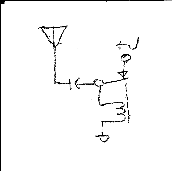
This is how we used to do it back in the stony ages:

enter image description here

\$\endgroup\$
2
  • 6
    \$\begingroup\$ For sure, drew circuit by pencil is one step toward stone age. Use stick on sand, hot iron on animal skin to fully matching the theme. \$\endgroup\$
    – EEd
    Commented Aug 4, 2014 at 20:48
  • 2
    \$\begingroup\$ @EEdeveloper: iron in stone age? c'mon... \$\endgroup\$
    – PlasmaHH
    Commented Dec 11, 2015 at 22:01
5
\$\begingroup\$

Is it possible to build a very minimalist radio transmitter that can be built only with passive components, what would be the schematics for that?

Yes this can be done using the energy from a battery switched to an inductor-capacitor tuned circuit. This would get you a form of morse-code transmitter but it wouldn't be that great and it would produce interference on other channels close by.

If you expected to transmit speech then forget it and add at least one transistor to get a quite reasonable FM transmitter.

\$\endgroup\$
2
  • 1
    \$\begingroup\$ As for interference, since ocean going ship phased out 500KHz and HF with Satcom, what real life user still there at these freq, presumable, 10 to 500KHz. I believe Time service (1xKHz, 66KHz?) and DGPS (3xxkHz) still in use, right? \$\endgroup\$
    – EEd
    Commented Aug 4, 2014 at 22:47
  • 1
    \$\begingroup\$ @EEdeveloper For the UK the band from 198kHz to 1602kHz is very widely used - mediumwaveradio.com/uk.php \$\endgroup\$
    – Andy aka
    Commented Aug 5, 2014 at 9:31
4
\$\begingroup\$

Yes in theory though it might be more trouble than it is worth. Heat up a strip of galvanized steel until it starts to sparkle indicating that the zinc is oxidizing. The resulting zinc oxide works as a crystal rectifier but it also has an amazing property called negative resistance. This allows it to be used as a replacement for a vacuum tube in a weak transmitter.

Google-fu or Yahoo-fu Crystodyne or the experimenter named Oleg Losev who developed the principle. Nyle Steiner does a lot of experimenting with forgotten tech like this. See this video. Also read this article by Hugo Gernsback.

\$\endgroup\$
2
  • \$\begingroup\$ +1 Good answer but need to break down into smaller paragraphs as I did. Use 'Google-fu or 'Yahoo-fu' to avoid signs of endorsements. \$\endgroup\$
    – user105652
    Commented Jul 1, 2016 at 3:31
  • \$\begingroup\$ SPARK BANG BUZZ is Nyle Steiner's project website for no-tech radio ocillators, sparkbangbuzz.com, in particular see this 40M ham band CW xmitter sparkbangbuzz.com/zinc-osc-2/zinc-osc3.htm. Steiner also builds tiny cold-cathode vacuum tubes without needing expensive diffusion or turbo pumps. \$\endgroup\$
    – wbeaty
    Commented Sep 18, 2016 at 0:03
2
\$\begingroup\$

This is early 1900 version, a great great piece of history.

Essentially an electromagnet (relay) with self on off contact and huge number of turns coils. You may be proud to re do the great history, with modern mini size components

http://www.youtube.com/watch?v=YSf93g0heUA

\$\endgroup\$
2
\$\begingroup\$

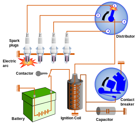
Another readily available method is use old car ignition coil and cam shaft switch breaker as this diagram (exclude the distributor) enter image description here (source)

\$\endgroup\$
1
  • 2
    \$\begingroup\$ I included the image in the post, stackexchange policy is to include as much as possible in the answer in case in the future external links go down \$\endgroup\$ Commented Aug 4, 2014 at 21:15
1
\$\begingroup\$

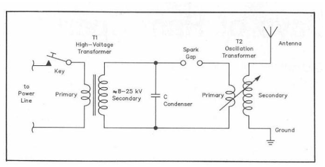
Because the spark gap transmitter is mentioned a lot in the answer but without a schematic diagram or detailed description of the working principles, I will include its schematic diagram.

enter image description here

The above schematic diagram along with the pictorial diagram, photos and the working principles can be found in this article(PDF). (here you can find a mirror of the same file at the Internet Archive in case the first ever goes down) This are here for education purposes because operating RF transmission equipment most of the time requires a license unless you do it in Faraday cage an nobody knows it ;).

\$\endgroup\$
2
  • \$\begingroup\$ It should be noted that operation of a spark-gap transmitter will by law be limited to power levels far below that of almost any other sort, because such transmitters will uncontrollably emit much of their energy at arbitrary frequencies unrelated to the primary frequency of interest. When the first transatlantic transmitter was constructed at Cape Cod, interference with other radio transmissions wasn't an issue, but that is no longer the case. \$\endgroup\$
    – supercat
    Commented Aug 5, 2014 at 15:33
  • 1
    \$\begingroup\$ Also, looking at the diagram, is the condenser in the right place? I would think one would want it to be part of the tuned circuit with the transformer and antenna. \$\endgroup\$
    – supercat
    Commented Aug 5, 2014 at 15:33
1
\$\begingroup\$

If a magnetron would meet your definition of a passive device, there will certainly be lots of them available for salvage, as few will find it worthwhile to run a generator in order to use one for cooking.

Your challenge might be more obtaining sufficient power, and building a receiver. And by the time you climb mountain peaks for line of sight communications, you might want signal flags and binoculars for backup.

On a similar theme, and perhaps more tailored to communications, there is the Gunn diode which has the advantage of being usable as both a transmitter and a downconverter (you can then use a broadcast receiver to demodulate the IF).

(I'd originally been thinking of ways to refine a spark gap with a resonator, then remembered there are physically resonant direct RF sources in wide use)

\$\endgroup\$
1
  • 2
    \$\begingroup\$ Scavenge the microwave - now that's a great survival story. You'll be out of popcorn in a matter of days, anyway. \$\endgroup\$
    – Floris
    Commented Aug 5, 2014 at 16:07
1
\$\begingroup\$

A Paulsen arc transmitter is also quite possible (And better in most ways then a spark gap set), this is a negative resistance oscillator using an arc in a hydrogen atmosphere as the active component.

I have actually built one for giggles, using alcohol evaporated by the heat from the arc and then broken down in the arc plasma to provide the hydrogen, carbon rods were from zinc carbon batteries, the tank inductor was wound around the legs of a chair and the tuning cap was made from two cardboard boxes and foil. Ballast resistance was an electric fire and bypass cap was made from foil and polythene sheet.

Not the worlds most efficient radio, but it worked, sort of, operating frequency was a couple of hundred KHz so you are talking BIG antenna structures.

There is also the flame diode, and even the flame triode which can provide gain and is very simple to construct out of junk, I expect you could probably build an RF oscillator out of such, and possibly even an amplified detector.

\$\endgroup\$
0
\$\begingroup\$

There were some antique incandescent light bulbs that would oscillate around 90 MHz due to the structure of the filament and resulting magnetic field. This could be exploited by placing the bulb in a tune-able resonant cavity and coupling the signal to an antenna. One could FM modulate the signal by varying the resonance of the cavity (a large hole with disk of aluminum foil as a microphone)

\$\endgroup\$
1
  • 2
    \$\begingroup\$ References? I can belive this is true, but would like to see more details if it is true. Power level and nominal range would be obvious details to add. \$\endgroup\$ Commented Sep 18, 2016 at 9:15

Your Answer

By clicking “Post Your Answer”, you agree to our terms of service and acknowledge you have read our privacy policy.

Not the answer you're looking for? Browse other questions tagged or ask your own question.