0
\$\begingroup\$

We have circuit like this:
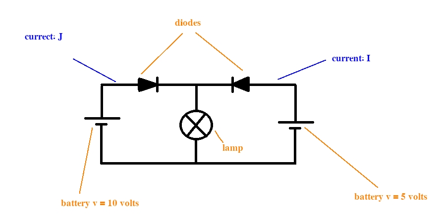
enter image description here

There's no internal resisters in batteries.

Is \$\frac{I}{J}\$ equal to zero? If it is nonzero what is the voltage between the ends of the lamp (assuming the lamp has almost infinite resistance)

\$\endgroup\$
9
  • 1
    \$\begingroup\$ Assuming ideal diodes, the voltage between the ends of the lamp will be 10V. The right diode will be reverse biased. \$\endgroup\$
    – 2over0
    Commented Aug 6, 2014 at 5:20
  • \$\begingroup\$ So will $$I=0$$? and will only left battery will be used? \$\endgroup\$ Commented Aug 6, 2014 at 5:25
  • \$\begingroup\$ I will be zero for an ideal diode. For a real diode there will be a small leakage current. \$\endgroup\$
    – John D
    Commented Aug 6, 2014 at 5:26
  • 1
    \$\begingroup\$ @MinimusHeximus Yes, this is a common configuration called "diode or-ing" and will work exactly as you describe. \$\endgroup\$
    – John D
    Commented Aug 6, 2014 at 5:31
  • 1
    \$\begingroup\$ The 10v battery would have to fall low enough (or be removed) for the rightmost diode to turn on and power the lamp. \$\endgroup\$ Commented Aug 6, 2014 at 5:32

1 Answer 1

1
\$\begingroup\$

An ideal diode analysis gives you an approximate answer:

  • The voltage across the lamp is approximately 9.3-9.5 V.
  • The diode carrying current I is reverse biased.

For a real diode, there will be some reverse leakage current through the "I" diode. This means I could be anywhere from -1 pA to -1 uA, depending on the type of diode. If you choose something like a Shottky diode to minimize the drop when the diode is forward biased, you will probably increase the amount of reverse leakage when it is reverse biased.

Final answer, in a realistic scenario \$\frac{I}{J}\$ will be a small but non-zero negative number.

\$\endgroup\$
5
  • \$\begingroup\$ Is it a good idea to replace the diodes with a transistor if the circuit is to work as a battery-selector? \$\endgroup\$ Commented Aug 6, 2014 at 16:24
  • \$\begingroup\$ How would you expect that to improve the circuit? I'm not being snarky, I mean you haven't told us enough about your requirements or what alternate circuit you are suggesting for us to know whether it would be better or not. \$\endgroup\$
    – The Photon
    Commented Aug 6, 2014 at 16:26
  • \$\begingroup\$ The diode circuit you have is quite adequate for many situations. \$\endgroup\$
    – The Photon
    Commented Aug 6, 2014 at 16:28
  • \$\begingroup\$ my comments above give more details. In fact I thought this circuit can be used in some situations. For example if I have two power supplies e.g. an AC-DC adapter and a battery I can use this circuit to use the battery only if the adapter is off. A good circuit sould not use or recharge the battery and have least voltage loss. So I'm asking if a transistor is a better substitute. \$\endgroup\$ Commented Aug 6, 2014 at 17:56
  • 1
    \$\begingroup\$ What transistor circuit do you have in mind? What signals do you have available to control the transistors? Remember that MOSFETs typically have body diodes so that they can't block "reverse" current. And a BJT used as a diode will have the same forward drop as a regular diode. But if you have appropriate control signals there might be circuits with slightly better efficiency than the simple diode circuit. \$\endgroup\$
    – The Photon
    Commented Aug 6, 2014 at 18:06

Your Answer

By clicking “Post Your Answer”, you agree to our terms of service and acknowledge you have read our privacy policy.

Not the answer you're looking for? Browse other questions tagged or ask your own question.