7
\$\begingroup\$

Background:

I follow a reference design for a single phase power meter (230 V, max 3 A). The below circuit is to measure current via a current transformer.
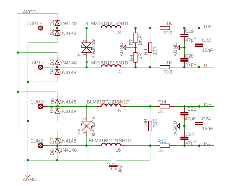
Enter image description here

  • A current transformer will be connected to the CUR1+/- andCUR2+/- terminals (two current transformers in total).
  • CUR1 and CUR2 are to measure current on phase and neutral
  • D1-D8 are for protection.
  • D9-D10 are for a transient voltage suppressor.
  • R9 and R10 are the burden resistors.
  • The right part of the R9 and R10 are anti-aliasing filters.
  • I1+/- and I2+/- are connected to an analog-to-digital converter of a microcontroller

I am planning to use this current transformer as it is one of the lowest-priced options on that supplier.

  • Turn ratio: 1:1000
  • Inductance: 8 mH
  • Current rating: 200 A
  • Secondary resistance: 26 ohms

Question:

The design does not specify what current transformer is used on the circuit and how I should calculate the burden resistors. It says maximum applied voltage to the ADC is ±920 mV.

  • How should I calculate the burden resistors R9 and R10? Do I need to consider the filter part while calculating the values?
  • I see different values for the secondary resistance. What is it important for? Is it used in the calculation of the burden resistors?
  • As I understood, the inductance's effect of the current transformer on reactive power will be corrected on a different stage. Apart from that, is the inductance matter for the above circuit?
  • It is a single-phase power meter. Is it enough to measure the current at only one current channel? If it is so, why would it be needed to have a measurement on both channels?
\$\endgroup\$
8
  • \$\begingroup\$ I'm not convinced that the circuit you show in the question is suitable for what you intend. Please explain more about the ADC you plan to use and why you require two channels for your CT. Without knowing your input voltage range, calculating a burden is pointless. \$\endgroup\$
    – Andy aka
    Commented Aug 7, 2014 at 12:55
  • \$\begingroup\$ Andy, could you please take a look at ti.com/lit/an/slaa517c/slaa517c.pdf page6 (3.2.2 is the explanation), Page 27 shows the implemented circuit, page 26 shows the I1/2 connections to the MCU (SD0P0, SD0N0) \$\endgroup\$
    – Angs
    Commented Aug 7, 2014 at 13:01
  • \$\begingroup\$ Your diagram doesn't seem to match TI's \$\endgroup\$
    – Andy aka
    Commented Aug 7, 2014 at 13:22
  • \$\begingroup\$ Do you mean the diagram on page 27 (sheet2/5)? \$\endgroup\$
    – Angs
    Commented Aug 7, 2014 at 13:25
  • \$\begingroup\$ I was looking at the one on page 6 \$\endgroup\$
    – Andy aka
    Commented Aug 7, 2014 at 13:44

2 Answers 2

2
\$\begingroup\$

Calculating the burden resistors for a commercial current-transformer is generally quite easy:

  1. Download current-transformer datasheet.
  2. Use values from datasheet.

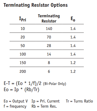
enter image description here

Chose the burden resistor that produces the desired voltage range for the current range you want to operate in.

Alternatively, if you really want to use your own burden resistor, the datasheet has that formula for you too!

\$E_{O} = I_{P} * \frac{R_{B}}{T_{R}}\ \$ where \$E_{O}\$ is the output voltage, \$I_{P}\$ is the current that will produce the voltage you want, \$T_{R}\$ is the transformer's turns-ratio, and \$R_{B}\$ is the burden resistance, in ohms.

As usual, read the datasheet. Most of your questions appear to be answered in the datasheet for the part you have apparently already chosen!


The reason the reference design you're looking at does not specify any of the parameters for the current-transformer is because it's designed to work with most any current transformer. You are expected to look up the relevant information on your current transformer.


Since you're only interested in single-phase metering, I'd just dump the CT entirely, and just use a shunt-resistor. I think that demo schematic has both just so you can try either, not because they're actually needed.

It's using a CT to get the needed isolation from the high-side of the mains. Since the circuit is referenced to one side of the AC mains, they can't easily use a shunt-resistor on the other side. The CT is a convenient, pre-isolated way to achieve this, but unless you're interested in multi-phase metering or something, it's rather overkill.

\$\endgroup\$
1
\$\begingroup\$

I would choose a CT with closer to 3A rated current than 200A if you're only interested in 3A max.

The current Transformer produces a current proportional to the current flowing though it's magnetic circuit. The proportion of the current in the cable that you get in the transformer is equal to the turns ratio.

For example : Current = 200A (rms) , Turns Ratio = 1000 => Transformer Current = 200/1000 = 200mA (rms). But at 3A that's only 3mA.

The CT07-1000 doesn't includes a burden resistor, so you need to have that in the circuit; R9, R10 as you pointed out.

At 200A in the example above, that corresponds to an output Voltage of 200mA x Rburden. So for 920mV ADC fullscale at 200A, Rburden = 0.92/.2 = 4.6Ohms . For 3A fullscale that's 306 Ohms.

Make sure the Current Transformer is only around the Live or Neutral NOT BOTH. If it's around both the magnetic flux in both the Live an Neutral will cancel to yield zero current in the Transformer. Also DO NOT attach or unattach the CT to a live cable with current flowing whilst touching the CT terminals. Attaching the CT will cause a Voltage spike across the CT of several kV possibly. This does not happen with CTs with an internal burden resistor.

The circuit you show looks overly complicated for a single phase 3A solution. Here's an example of a project I did which seems similar to your requirements that may be of some help to you.

enter image description here

\$\endgroup\$

Your Answer

By clicking “Post Your Answer”, you agree to our terms of service and acknowledge you have read our privacy policy.

Not the answer you're looking for? Browse other questions tagged or ask your own question.