3
\$\begingroup\$

I am extremely new to using Eagle (or creating circuits in general). I've been searching around online for tutorials on making your own parts in eagle. However, I still have a few questions and I was hoping to get some clarification.

For reference, I've been trying to build this 28-pin IC socket:
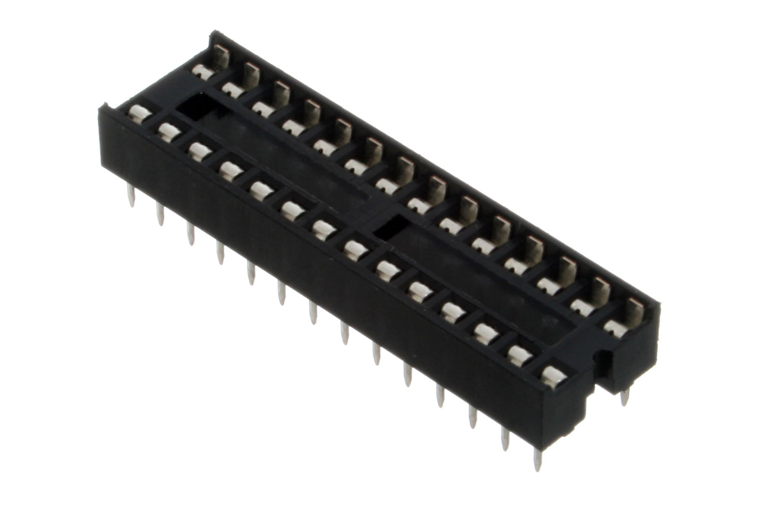
the part

I was unable to find one of these in the default eagle libraries, so I am trying to make my own.

As far as I can tell, making a part consists of three parts: making the symbol, making the device, and making the package. I know that the symbol is simply what appears in the schematic and doesn't really have to exactly match the size or shape of the real part. I don't, however, really understand what the package and device are. I know they relate to the real part id and the size and shape of the part on the board. Can I please get some clarification on what the package and device correspond to and why I need to make them?

Also, when looking for parts using the design link, I often struggle to find the part I'm looking for. Is there a way to view the database eagle's design link is using in a browser rather than in that dialog box? It would make things much easier for me when looking for a specific part.

\$\endgroup\$

1 Answer 1

3
\$\begingroup\$

Generally if you can't find the part, you'd have to make it yourself. There are many tutorials explaining how to make a part in Eagle.

You are correct in discerning between the three categories for an Eagle part.

Schematic symbol: This is the representation of your part as it will appear in the schematic. It doesn't have to have all the pins represented exclusively, like say if there are multiple GND pins.

Footprint/package: This is what the devices physically looks like and how it will appear on your circuit board. Each solderable pin must be represented here. You need this so you can actually place the part on your PCB.

Device: This is the middle ground between the two, while you never place a device, it is how the schematic symbol will connect to the foot print in the software. You need this because a connection made in a schematic represents a physical connection on the circuit board. If you connect a signal to a pin of a symbol in the schematic editor, the software needs to know to make the same connection on the circuit board.

You'll notice, after you've made a schematic that has connections, that when you start to design your circuit board, you'll see many yellow lines, these are called "air wires" and are un-routed representations of the signals created in the schematic. In the PCB editor, you are just making the connections you made in the schematic editor a physical track that will be on your circuit board when you have it fabricated.

For this part specifically, I know this has been made and released since I use it all the time and I didn't make my own. Sparkfun releases many of the parts used in their products in the form of the footprint and schematic symbol. It seems like they have a DIL28 connector in their connections library. You can download them from the linked github page.

As for more Eagle library resources:

\$\endgroup\$
5
  • \$\begingroup\$ I appreciate the info! I cannot seem to find the DIP-28 part in the connectors library, however. Can you please point me in the right direction (part number or something of the like)? \$\endgroup\$
    – user50333
    Commented Aug 14, 2014 at 17:22
  • \$\begingroup\$ Oh sorry, in the connectors library its called DIL28, I'll edit my answer \$\endgroup\$
    – Funkyguy
    Commented Aug 14, 2014 at 17:23
  • \$\begingroup\$ Hey one last question if you're still around, is there a way to view the design link database in a browser? Or is my perception of how the design link database works incorrect? \$\endgroup\$
    – user50333
    Commented Aug 14, 2014 at 19:05
  • \$\begingroup\$ That I am unsure about. I have never used the design link functionality. \$\endgroup\$
    – Funkyguy
    Commented Aug 14, 2014 at 19:06
  • \$\begingroup\$ @Funkyguy addressing your comment, there is a website that has a database for Eagle parts. You can search by footprint, device, number of pins, pads, etc. Listed as "experimental" for now, it worked for me. For example, I needed a 40 pin QFN in a 5x5mm package, and the website pointed me to the 'texas' library. On the other hand, when I use Eagle to search through the libraries for anything QFN-related (using wildcard search as *QFN *), the TI part does not show up. sparkle.tribbeck.com/eaglesearch2/index.php \$\endgroup\$
    – ADB
    Commented Feb 11, 2015 at 21:32

Your Answer

By clicking “Post Your Answer”, you agree to our terms of service and acknowledge you have read our privacy policy.

Not the answer you're looking for? Browse other questions tagged or ask your own question.