0
\$\begingroup\$

I am currently trying to use a 5 Pin relay on a Motorcycle indicator circuit. The concept is I have a Daytime Running Light (DRL) that is in the same housing as the indicator. When the indicator is on, I would like the DRL to go off.

So far, I have wired a 5 Pin Relay with a Capacitor as the current from the indicator is not constant (As the indicators have to flash). Initially I tried building this circuit without a Resistor. However, either my capacitors are not big enough (Tried 1000uf & 4700uf) or they are discharging too quickly without the resistor.

Relay is 20/10amp 12v with a current draw of 0.15amp.

How do I work out what size resistor I need?

The current circuit is like this

Indicator Wire --> 1w Diode --> 16v Capacitor (1000uf or 4700uf) --> 5 Pin Relay

I need the capacitor to output enough current to keep the relay open (NC Relay) for approximately 1/2 second (between the flashes of the indicator).

\$\endgroup\$
3
  • \$\begingroup\$ Do you have any information about the relay? Your question is difficult to answer without more information. \$\endgroup\$
    – user49628
    Commented Aug 14, 2014 at 23:36
  • \$\begingroup\$ This is the link to the manufacturer website for the relay. Part no. 68070 narva.com.au/products/browse/micro-relays \$\endgroup\$
    – Andrew Hui
    Commented Aug 15, 2014 at 0:32
  • \$\begingroup\$ Please post your complete schematic or wiring diagram in whatever form you can. Questions like this are notoriously susceptible to silly misconceptions about how things should be wired, that are difficult to flush out with just a verbal description. \$\endgroup\$
    – gwideman
    Commented Aug 15, 2014 at 1:12

2 Answers 2

2
\$\begingroup\$

I think adding a resistor will defeat your purpose. The relay's coil serves as a resistor, shunting off the capacitor's charge. Add a resistor in series with the coil and you may not have enough current to activate the relay. Add a resistor in series with the capacitor (parallel to the coil) and your capacitor may not build up enough charge to do much of anything. Add a resistor in parallel with both the coil and the capacitor, and you're just pulling more current (besides discharging your capacitor even faster).

The coil here is equivalent to a resistor in a simple RC network. Its resistance is 12V / .15A = about 80 ohms. Through experimentation (there's no good way to do this part through calculation), determine how low the voltage can go without dropping out the relay. Now from THAT you can calculate your timebase - how long does it take a 1000uf capacitor to drain from 12V down to (the dropout voltage) through an 80-ohm resistor? Not very long.

If you add too large a capacitor, though, CHARGING it through your indicator may damage the indicator, the blinker, or the switch... and will almost certainly blow the fuse.

Try powering the relay from a 555 timer, preferably with a driver transistor. That takes a MUCH smaller capacitor to accomplish the same goal, uses far less current, and gives you some more soldering experience. 8)

\$\endgroup\$
7
  • \$\begingroup\$ How would you wire the 555 into the existing circuit? \$\endgroup\$
    – EM Fields
    Commented Aug 15, 2014 at 7:02
  • \$\begingroup\$ I'd set it up as a classic monostable multivibrator, with the OUT pin driving the driver transistor that powers the relay. TRIG would be held to VCC. The indicator would drive a small transistor that bypasses C, so when the indicator is powered, the transistor shunts C, starting a timing cycle. When the indicator blinks off, C is allowed to recharge but R is chosen such that C never reaches 2/3VCC before the blinker turns on again, shunting C back to ground again. When the indicator turns off for longer than one blink cycle, C charges fully & permits the DRL to light. \$\endgroup\$ Commented Aug 15, 2014 at 11:13
  • \$\begingroup\$ That won't work because - no matter what you do with the timing cap - if TRIG is wired to Vcc it'll be impossible to drive OUT high. \$\endgroup\$
    – EM Fields
    Commented Aug 15, 2014 at 17:23
  • \$\begingroup\$ Not true. TRIG is active LOW. Try it. \$\endgroup\$ Commented Aug 15, 2014 at 17:32
  • \$\begingroup\$ TD: I don't believe TRIG being active low has anything to do with it, but you're right - OUT goes high when THR is > 2/3VCC and TRIG is >1/3 VCC, but only once. Take a look at a 555 front end and you'll see that TRIG and THRESH are the signal inputs of a window comparator which sets and resets an RS latch depending on where TRIG and THRESH are. Bottom line is that if TRIG is sitting at > 1/3VCC and THRESH rises past 2/3 Vcc, the latch'll be reset, OUT will go low, and that state will persist until TRIG goes lower than 1/3 VCC and THRESH goes lower than 2/3 Vcc, so your way can't work. \$\endgroup\$
    – EM Fields
    Commented Aug 15, 2014 at 20:47
1
\$\begingroup\$

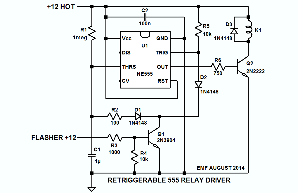
Assuming a 12V signal from the flasher and hot 12VDC available in the housing, the schematic below shows a circuit that should work, and if you want to play atround with the circuit, the LTspice circuit list is here

enter image description here

\$\endgroup\$

Your Answer

By clicking “Post Your Answer”, you agree to our terms of service and acknowledge you have read our privacy policy.

Not the answer you're looking for? Browse other questions tagged or ask your own question.