1
\$\begingroup\$

The theory (that I know) goes like:

Two junctions, EBJ and CBJ, EBJ is put in forward bias and CBJ is put in reverse bias to operate the BJT in forward active operation Region.
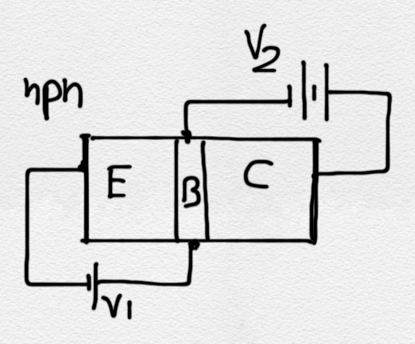
Diagram 1

Now Electrons are injected at Emitter by battery V1, nice, let's say 100 electrons went out of V1.

Now since base is seriously thin, and there is strong electric field of CB junction, we can safely say that only 10 electrons were able to reach the base terminal and finally back to battery V1.
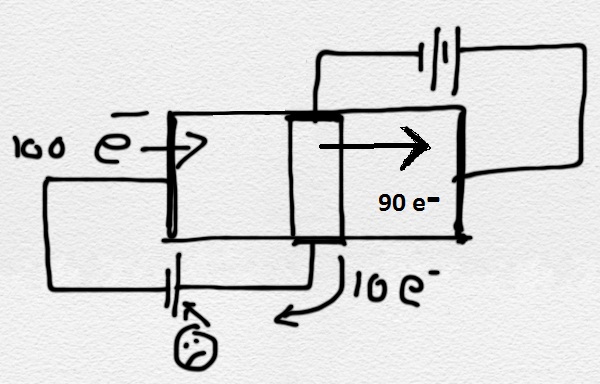
enter image description here

The other 90 electrons were collected by V2 who didn't even give any electrons.

From what I know of batteries, I think that if I take 100 electrons out of -Ve terminal then I also got to give it back 100 electrons at +Ve terminal. Isn't that so?

My question is Where am I going wrong? How can V1 keep losing electrons and V2 keep pirating V1's electrons and the system still works?

\$\endgroup\$
4
  • \$\begingroup\$ A transistor won't operate as a transistor the way you have V2 connected. V2 needs to collect the 90 electrons via the collector and then return them to the most negative point on the system namely the negative end of V1. \$\endgroup\$
    – Andy aka
    Commented Aug 22, 2014 at 16:36
  • \$\begingroup\$ @Andyaka Ohh I made a terrible mistake in the drawing (I've provided the corrected image now). Still I just fail to see how those electrons will ever return to V1. \$\endgroup\$
    – vyi
    Commented Aug 22, 2014 at 16:44
  • \$\begingroup\$ Redraw it first. All the base electrons will exit via the emitter. With Vbe set right there will also be current flowing from collector to emitter. So base current is Ib, collector current is Ic and emitter current is Ib+Ic. (And all your sad electrons are saved :^) \$\endgroup\$ Commented Aug 22, 2014 at 16:48
  • \$\begingroup\$ @GeorgeHerold Can you please help by drawing some electrons on this template image npn_img \$\endgroup\$
    – vyi
    Commented Aug 22, 2014 at 16:55

1 Answer 1

3
\$\begingroup\$

My question is Where am I going wrong?

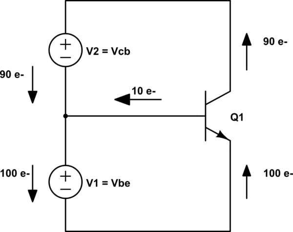
I've redrawn your circuit

schematic

simulate this circuit – Schematic created using CircuitLab

so that is clear that all of the emitter current is through the base-emitter source.

Remember there is only one base terminal so the way that you've drawn the circuit, with the voltage sources connecting to 'opposite sides' of the base, is misleading you - the base and two voltage sources connect to a single node as I've shown.

The '90 electrons' from the collector flow through \$V_2\$ and then through \$V_1\$ joined by the '10 electrons' from the base.

\$\endgroup\$
5
  • \$\begingroup\$ This is very neat and clear. I have one more doubt, that if there exists a npn transistor as drawn by me (with two opposite base terminals), will that fail to work in reality (when operated in the same way as I have put up two batteries in diagram) ? \$\endgroup\$
    – vyi
    Commented Aug 22, 2014 at 17:29
  • \$\begingroup\$ @vvy, I'd need more details on the device construction etc. to answer that. \$\endgroup\$ Commented Aug 22, 2014 at 17:34
  • \$\begingroup\$ As I keep looking into the circuit I am seeing new details and doubts.. What compels those 90 electrons to come back, it should be the emf of V1. right? What do we call the outer loop (containing V1, V2 and transistor C and E terminal), any specific name? Can one apply KVL on this loop. \$\endgroup\$
    – vyi
    Commented Aug 22, 2014 at 18:15
  • \$\begingroup\$ @vvy, KVL is trivial around the outer loop: \$V_{CE} = V_{BE} + V_{CB} = V_1 + V_2\$. I'm not sure I understand your doubts. Think of the collector current ('90 electrons') as circulating around the outer loop while the base current circulates around the lower loop only. The elements in common with both loops carry the sum of the two currents. \$\endgroup\$ Commented Aug 22, 2014 at 18:55
  • \$\begingroup\$ Its a relief. I guess, my understanding now isn't shaky, I hope I will now be able to study and understand well the theory of BJT operation in various modes and feedback analysis. Thanks you. \$\endgroup\$
    – vyi
    Commented Aug 23, 2014 at 11:29

Your Answer

By clicking “Post Your Answer”, you agree to our terms of service and acknowledge you have read our privacy policy.

Not the answer you're looking for? Browse other questions tagged or ask your own question.