2
\$\begingroup\$

We're using an LM317BTG to power a 4V modem (the LM is connected to a 12V battery). The modem can produce peak currents of up to 2A during transmission bursts. Under normal operations, the modem consumes anywhere between 100mA and 300mA.

We would like to be able to switch the LM317BTG on/off using a microcontroller (digital IOs rated at 5V/couple of mA).

I'm thinking a transistor of some sorts could be used here? I've already used NPN bipolar junction transistor (BJT) (like the 2N2222) to switch low-power devices on/off but I guess I need something more powerful than that?

Do I need to use a MOSFET, or is a Darlington also possible? And how should I hook it up in the circuit? I would like to use a digital IO of the microcontroller (0V or 5V) to switch the LM317BGT on/off.

\$\endgroup\$
2
  • \$\begingroup\$ There isn't really such a thing as switching an LM317 off. You could put a switch before it, but then the question isn't about the LM317 at all. \$\endgroup\$
    – user207421
    Commented Aug 30, 2014 at 23:20
  • \$\begingroup\$ As pointed out in the accepted answer, there is an LM317 specific solution possible using the ADJ pin so in that sense it is LM317 specific. \$\endgroup\$
    – ddewaele
    Commented Aug 31, 2014 at 10:26

2 Answers 2

5
\$\begingroup\$

If you pull the ADJ pin to ground with a transistor you'll reduce the output voltage to 1.25V. If that's good enough, all you need is a transistor like a 2N2222 with a base resistor (note that the base will draw current to turn the regulator off). It will still draw current, but it should be reduced quite a bit (the regulator with resistors will draw at least 5mA itself and the MODEM will probably draw some current at 1.25V).

If you want to shut it down entirely you could use a MOSFET high-side switch, which would involve a P-channel MOSFET and a transistor (BJT or MOSFET) to level shift the logic signal. It would not draw current other than leakage when off. If two transistors, a few resistors and a zener sounds too complicated for you, you could use a MOSFET SSR. The input is an LED so you would need to add a resistor to the output of your micro to limit the current. It should be rated for the peak current of your MOEM.

However, at 100-300mA continuous, I suggest you bin the LM317 and use a switching regulator with an ON/OFF pin. That would reduce the OFF current to tens of uA or better, and the efficiency when operating would be greatly increased. The regulator (such as LM2576) will typically have a logic-level compatible control pin so you can connect it directly to the micro.

There also exist linear regulators with ON/OFF inputs if you'd prefer.

\$\endgroup\$
2
  • \$\begingroup\$ PCB currently supports either an LDO or a switching regulator (with an On/Off Inhibit pin). So the switching regulator solution is straightforward but would like a feel for the LDO solution (LDO solution being a lot cheaper from a power-supply perspective) \$\endgroup\$
    – ddewaele
    Commented Aug 30, 2014 at 13:47
  • \$\begingroup\$ I don't think that it will be cheaper once you add the high side switch. Plus, your efficiency can't be higher than about 41% with a linear regulator, so you're throwing away battery capacity. \$\endgroup\$ Commented Aug 30, 2014 at 13:51
5
\$\begingroup\$

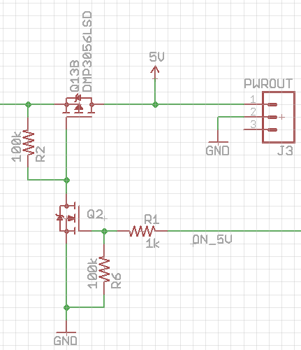
I'm inclined to agree with Spehro here - you are better off with an LDO or a switching regulator that come with an ENable pin. However, having just done this myself I'll add a picture of what my high side P Mosfet switch looks like (cropped quickly from a larger schematic):

enter image description here

In this case the power input is the line coming into the P mosfet on the left. The line labelled ON_5V is coming from a PIC16F88 microcontroller running at 3.3V. Q2 is a BSS138. R1 probably isn't necessary.

Both Q2 and Q13B were the components I had to hand that supported switching at the voltages I'm using and you'll have an easier time choosing a P mosfet if your input voltage is 12V - gives you plenty of gate drive.

I had 50 BSS138s on my desk so I'm using them everywhere - they turn on at 1.2V or so and 3.3V is no problem. Bear that in mind when choosing one - it needs to turn on at the logic level you are using. Hope this helps.

\$\endgroup\$
2
  • 1
    \$\begingroup\$ +1 Looks good. I'd add a series resistor of a few K from the drain of Q2 and a 12-15V zener from source to gate of Q1 so the 20V abs max rating Vgs of Q1 can't get exceeded even if there's a spike on the 12V. \$\endgroup\$ Commented Aug 30, 2014 at 15:52
  • 1
    \$\begingroup\$ Good point on the zener. I had a schematic note somewhere to put a resistor in the drain but I was rushing at the time. For much the same reason as I have R1 in there I'll put one in next time. Thanks for the reminder actually! \$\endgroup\$
    – carveone
    Commented Aug 30, 2014 at 16:02

Your Answer

By clicking “Post Your Answer”, you agree to our terms of service and acknowledge you have read our privacy policy.

Not the answer you're looking for? Browse other questions tagged or ask your own question.