2
\$\begingroup\$

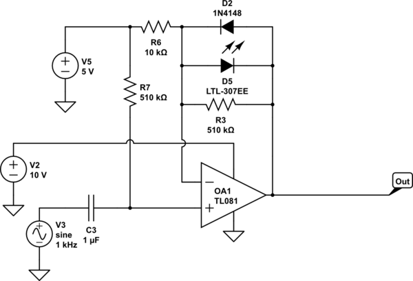
Below is a basic implementation of a circuit used to clip an incoming signal using the diodes in the feedback loop of the op-amp. Since the diodes are different they have different characteristics, specifically Vf which causes each one to start conducting at slightly different voltage. The diodes are also placed in opposite to each other so one may conduct on the positive half of the wave and the other on the negative (given the input signal and gain product is high enough).

Each one of the diodes will start conducting when the voltage between the inverting input and output of the op-amp exceeds its Vf.

I would like to modify the circuit so it would behave in the same manner but I will be able to control the DC offset at one end of the diode.

For example, you can see that the input is bias with a 5V DC voltage, so a diode starts conducting when the voltage reaches 5V + Vf. I would like to be able to adjust the bias voltage over a small range so that a smaller signal and gain might cause clipping or the other way around.

I would like to do this without moving the diodes outside the feedback loop. I tried inserting a simple series resistor after the didoes and it seems to me that by altering the value of the resistor I can obtain the effect I want but in practice this does not work well enough and interfere with the gain of the circuit which I don't want to change because of the diode adjustments.

I'll appreciate suggestions if this is possible.
schematic

simulate this circuit – Schematic created using CircuitLab

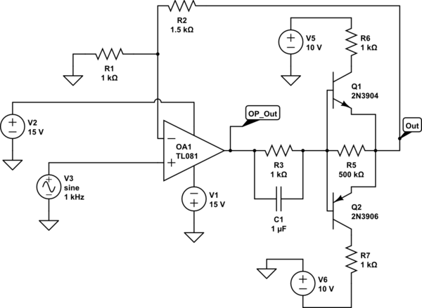
OK so here is the circuit suggested in an run-able and edit-able version :)
schematic

simulate this circuit

\$\endgroup\$
3
  • \$\begingroup\$ What are you after? A clipping cct without varying gain? You could buffer the output with a push-pull stage powered from different rails and close the feedback loop around the push-pull \$\endgroup\$
    – user16222
    Commented Sep 1, 2014 at 7:55
  • \$\begingroup\$ @JonRB - I'm after a clipping circuit where I can change the threshold voltage without affecting the gain by doing so. \$\endgroup\$
    – user34920
    Commented Sep 1, 2014 at 9:13
  • \$\begingroup\$ Analog Devices AN-106 "A Collection of Amp Applications" by James Wong: Figure 37 (last page) \$\endgroup\$
    – Tut
    Commented Oct 2, 2014 at 13:18

2 Answers 2

1
\$\begingroup\$

How to provide a variable clamp while keeping OPAMP gain the same.

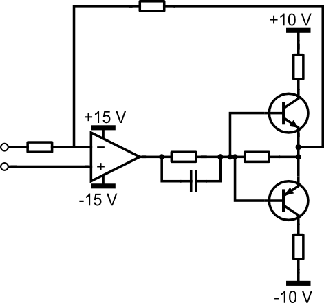
An output push-pull stage powered from separate rails/references is able to provide clamping capability independent of OPAMP gain (within the range of the clamp)

enter image description here

\$\endgroup\$
2
  • \$\begingroup\$ Please see my updated original post. The idea is to change the voltage rails of the transistor so they will be lower than the op-amp's output thus clipping the signal? I see the cap on the output to allow a low impedance path for the AC signal I assume? What about the resistors? Why this configuration? \$\endgroup\$
    – user34920
    Commented Sep 1, 2014 at 11:37
  • \$\begingroup\$ The cap is a speedup cap. If you are always after clipping the rails to the output clamp could be provided by opamps with a less than unity gain. But if as you describe you always want it to clip and equally reduce... Then the output will tend towards zero. What exactly are you trying to achieve \$\endgroup\$
    – user16222
    Commented Sep 1, 2014 at 11:41
0
\$\begingroup\$

You can also use front to back Zener diodes in the feed back path. Described in detail by Bob Pease here.

\$\endgroup\$
3
  • \$\begingroup\$ Link-only answers are not appreciated here. At least put the basics of the answer here, then you can refer to a link for more background information. \$\endgroup\$ Commented Sep 1, 2014 at 13:26
  • \$\begingroup\$ not only that but the clamping can't easily be changed and is limited to the decimation of zener voltages - not knocking zener clamps, use them all the time for OPAMP integrators BUT it would not satisfy what the original question asks for \$\endgroup\$
    – user16222
    Commented Sep 1, 2014 at 14:06
  • \$\begingroup\$ Hi @JonRB, (Have you read the article?) Figure 6. shows an "IC" zener in a bridge that I think could be used for variable clamping. (Maybe a TL431) And he has some active clamp circuits, with diode's and opamps in the feedback path. \$\endgroup\$ Commented Sep 1, 2014 at 14:23

Your Answer

By clicking “Post Your Answer”, you agree to our terms of service and acknowledge you have read our privacy policy.

Not the answer you're looking for? Browse other questions tagged or ask your own question.