3
\$\begingroup\$

I am not asking how the battery gets damaged, because that answer is straightfoward.

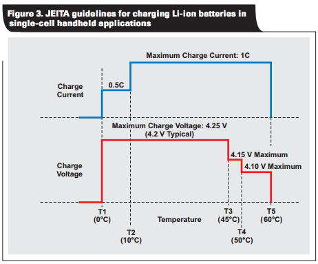
What I am asking is why lithium-ion chargers allow batteries to be damaged by excessive charge current in the first place. My understanding is that all lithium-ion chargers already support current limiting features in response to battery temperature (e.g. as part of "JEITA compliance"):

JEITA guidelines for charging Li-ion batteries in single-cell handheld applications

So why don't the chargers also enforce the maximum charge current, regardless of the wattage of the input power supply?

UPDATE

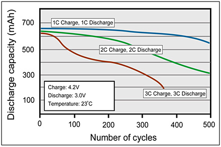
Putting the question a bit better: considering the huge number of handheld devices that integrate the charger and the battery, why don't charger ICs offer the ability to set a maximum charge current to be enforced? Why don't device manufacturers want to protect their batteries in this way?

current vs lifetime

\$\endgroup\$
3
  • 1
    \$\begingroup\$ I would say it's because they don't know how much 1C should be. \$\endgroup\$ Commented Sep 2, 2014 at 20:49
  • \$\begingroup\$ I have added a new 1st paragraph to my answer. The answer was correct as it stood but did not clearly enough address your JEITA guidelines point. \$\endgroup\$
    – Russell McMahon
    Commented Sep 3, 2014 at 13:23
  • \$\begingroup\$ @IgnacioVazquez-Abrams - That's a fair point, but given that most charger ICs provide ways to set various other options, I'm confused as to why the overall max current would not be a settable option as well. And in the case of integrated systems (mobile devices), 1C is definitely known in advance; why are these not properly limited? \$\endgroup\$
    – Ian
    Commented Sep 3, 2014 at 15:22

3 Answers 3

3
\$\begingroup\$

Short:

Important: Note that the reduction in maximum charging voltage with battery temperature is only of relevance when the battery is in the final stage CV (constant voltage) charging mode. For the majority of a charge cycle the battery is in CC (constant current) mode and the charging voltage is below Vmax - so the charger's CC limit has to be correct for the battery - altering the V in CV mode will not help at this point.

Systems which allow the charger to determine battery capacity generally do not damage the battery by overcharging. Where this does happen it will generally be because the charger cannot determine battery capacity and assumptions have been made which are violated by subsequent user or supplier actions so that a lower capacity battery than the designer has assumed are installed.

I have seen computers which charge without damage not only LiIon batteries of different capacity but also of different terminal voltage in the same machine. I do not know how general this capability is but it is both sensible and impressive.


Longer:

Lithium Ion / Lithium Polymer batteries are usually charged in two stages - first a constant current (CC) mode where the current is by design limited by the charger and then a constant voltage (CV) mode where the current is limited by the battery.

The maximum current allowed in CC mode for a given battery is set by the battery manufacturer. This is typically 1C but in some cases may be as little as C/2 and I have seen 2C quoted. I suspect that 2C may require special magic as if it was realistically achievable without compromising cycle or capacity lifetimes more manufacturers would offer it.

If a charger "knows" what the C capacity of the provided battery is then it can limit CC to the required C rate. Intelligent battery-charger arrangements can and do do this. It is possible to buy batteries of different capacity for the same computer or other equipment. If the equipment is unable to determine battery capacity it will necessarily treat it as having the designed capacity. Larger batteries will charge at < design C rate and smaller capacity batteries will be charged at higher than design C rate and will probably be damaged.


In very simple terms:
(Very non-technically put - mainly just remember - "don't do it, it's bad" :-) ).

As well as thermal effects mentioned in the cited article maximum charge rates relate to the ability to properly "put the Lithium where it belongs" in the battery structure. Excessive charge rates can end up with pure metallic lithium 'where it ought not be' with capacity effects at best and vent with flame at worst. Among other things LiIon battery lifetimes are due to the structure being mechanically flexed as Li is moved around the cell. LiFePO4 cells avoid this issue by having a permanent olivine structure which the Li is 'moved' in and out of - with a resultant reduction in available energy storage capacity due to the inactive material.

\$\endgroup\$
2
  • \$\begingroup\$ (This question hit 1000 views and I got a notification.) You've noted that the charger attempts to determine 1C for the battery, because the charger doesn't know what battery it's connected to. But the device that contains the battery knows what the battery is, so why not use the device to enforce 1C (between the charger port and battery terminals)? What's the reasoning there, given (as you pointed out) the risk of fire if the wrong charger is used? \$\endgroup\$
    – Ian
    Commented Feb 12, 2019 at 13:03
  • \$\begingroup\$ @Ian This is essentially covered by my 2nd paragraph: "Systems which allow the charger to determine battery capacity generally do not damage the battery by overcharging. Where this does happen it will generally be because... assumptions have been made which are violated by subsequent user or supplier actions so that a lower capacity battery than the designer has assumed are installed." -> (bolding added here). ie what you suggest is in fact what is done (usually :-) ) by the original designer. Problems occur only when the battery size is reduced subsequently. \$\endgroup\$
    – Russell McMahon
    Commented Feb 15, 2019 at 20:06
3
\$\begingroup\$

Read your link more carefully. Fast chargers can cause damage; connecting a larger power supply to a correct charger will not. As you say, the charger limits the current. That's what it's for.

Terminology is confused by the public calling USB power supplies "fast chargers".

Edit in response to comment: The following uses "USB power supply" to refer to the thing that plugs into the wall and "charge controller" to refer to the charge monitoring system inside the iPad. This is not the same as the terminology in common use, but it's more correct.

Suppose that the battery's 1C current is 2A. The device is then designed with a charge controller that allows up to 2A into the battery. It is shipped with a USB power supply capable of delivering 2A. It charges quickly at 2A, limited by the controller, and everyone's happy.

Note that the USB voltage will be 5V but the battery terminal voltage will be <4.2V.

Someone then connects a different USB power supply. These are normally limited internally to 500ma. The device charges at 0.25C more slowly.

I get impatient and connect it to my bench power supply capable of supplying 10A. The charger is now not limited by the power supply, but by the internal charge controller. It draws 2A and charges at the "fast" speed.

Older mobile phones and other devices put the charge controller and the power supply in the same brick that plugs into the wall, and do not do their own current limiting.

\$\endgroup\$
4
  • \$\begingroup\$ Your answer is confusing. It's easy to demonstrate that some USB chargers can charge faster than others. And it's been shown that charging with more than 1C current reduces the life of the battery. So how can the charger be limiting the current if the device actually charges faster with the higher-current supply? \$\endgroup\$
    – Ian
    Commented Sep 3, 2014 at 15:36
  • \$\begingroup\$ The charge current is the maximum allowed by either the charge controller or the USB power supply. I'll add an edit. \$\endgroup\$
    – pjc50
    Commented Sep 3, 2014 at 15:40
  • \$\begingroup\$ The device charges the battery at the maximum rate (which is probably 1C) when it has enough power from the USB adapter to do so. If the USB adapter can't provide that much power, the device charges the battery at a lower rate. For most devices, the charging rate doesn't go above 1C regardless of how much power the USB adapter can provide, because the the battery charger circuit inside the device also limits current into the battery. \$\endgroup\$
    – Matt B.
    Commented Sep 3, 2014 at 16:49
  • \$\begingroup\$ The USB adapter circuit provides (or limits) current into the device, then the device battery charger circuit provides (or limits) current into the battery. There are two regulators and current has to get through both of them to reach the battery. \$\endgroup\$
    – Matt B.
    Commented Sep 3, 2014 at 16:51
1
\$\begingroup\$

There are some misconceptions in your question.

1) USB wall adapter and battery charger are the same thing?

No, they are different circuits. The AC-to-USB adapter for a phone or similar device is the equivalent of the wall adapter to a laptop, it provides a stable voltage from which everything inside the device runs. The voltage output will be 5.0VDC and current capability may range something like 0.5A to 2.0A depending on the model. The official USB 2.0 spec a few years ago was capped at 0.5A per port, but Apple made their own customized version in order to provide more power to charge the iPad faster. Many third party vendors reverse engineered and copied the design modification, so 2A USB adapters aren't unusual now. A new official USB 3.1 spec ranging up to 20V x 5A = 100W is on the horizon for future devices. See Wikipedia on USB Power.

Meanwhile, the actual battery charger circuit is inside the device. It takes the USB adapter output as its input and regulates it (again) to what the battery should have as a charging input. For a lithium polymer battery the charger limits both the voltage and current into the battery, with voltage limit set to something like 4.0 to 4.2V and the current limit to a 1C rate at most, for a 1 hour charge. Likely somewhat slower in order to do as little damage to the battery as possible while giving the user an acceptably fast charge time. Some algorithms go quickly for the first 80% full and slower for the last 20% full.

2) The USB adapter sets the charge rate of the battery?

The USB adapter doesn't say to the device "charge at this rate," it says "this is how much power I can put out" and the device adjusts itself accordingly. The maximum power level is supposed to be negotiated between device and host according to the USB spec, starting from a minimal level and granting the device more power upon request. For details see the USB Implementers Forum and this StackEE post. In practice, some (most?) hosts offer the maximum of which they're capable at all times the port is switched on. Apple's proprietary scheme involves pullup & pulldown resistors on the data lines to signal how much power is available. The upcoming USB 3.1 spec may handle things differently.

The USB adapter only affects the charge rate if it forces the charger to go slowly because it doesn't have enough power input to charge as fast as it would like. For example, an iPad Air ships with a 5V x 2.4A = 12W adpater, has a 32.4W-hr battery, and thus could not charge any faster than 32.4/12 = 2.7 hours or about a C/3 rate (not 3C rate). With efficiency losses, slower charge after 80%, etc., it's more like a 4 hour charge from 0% to 100%. Reference: AnandTech. If you plug the same iPad into a smaller iPhone USB adapter which can only output 5V x 0.5A = 2.5W, you'd necessarily see something like 5x longer charge time because the adapter is only putting out 1/5 the power. Presumably the results are similar for other combinations of device and port, BUT with a badly designed device &/or adapter it could be the case that a heavy load simply overloads the adapter and trips a fuse, or worse.

3) Device makers charge at 3C rate or "don't care" about damage to battery?

Reputable device makers care very much about damage to the battery. A badly designed product can literally catch on fire. There may be a big difference in quality or reputation management between a large public company and a no-name brand from a distant corner of the world. Nonetheless it's not typical to charge at 3C except in devices specifically designed for it (using a high-rate battery) such as cordless drill. The chart you reference was probably created in a test lab where the batteries were charged and discharged directly on battery testing equipment set to harsh parameters to see what would happen, not in a consumer device.

4) Charger ICs don't allow setting maximum charge current?

The ICs do allow such setting. They have to permit the charge current to be set somehow by the device designer in order for the chip to be used in a broad range of devices. Have a look at the data sheets for chips from Texas Instruments, Maxim, Linear Tech. In a phone this function may be integrated into the power management IC rather than a standalone charger IC. Again, this is handled by the device, not the wall adapter.

\$\endgroup\$
3
  • \$\begingroup\$ (This question hit 1000 views and I got a notification.) The battery may be able to draw more than 1C, and the power supply may be able to deliver more than 1C. In that situation, does the charge circuit intervene, limiting the current to 1C (+/- some allowable margin)? My conception is (or was, in 2014) that they did not, leading some manufacturers to warn against rapid charging. Was that incorrect? (Now that it's 2019, my research suggests that fast charging is no longer a problem.) \$\endgroup\$
    – Ian
    Commented Feb 12, 2019 at 13:32
  • \$\begingroup\$ Yes, the battery charger circuit is between the wall adapter and the battery, and controls what current goes into the battery. That is what the battery charger circuit is there to do. Wall adapter = {Wall AC --> some regulated voltage with max current capability}, this is outside the device. Inside the device, that regulated voltage goes to the input of other circuits. One circuit controls current into the battery. Others may control max voltage allowed to the CPU or other areas. The wall adapter output is "raw material" for downstream circuits to further control. \$\endgroup\$
    – Matt B.
    Commented Feb 14, 2019 at 1:53
  • \$\begingroup\$ It is (hypothetically) possible to design a device that applies wall adapter output directly to the battery with no further regulation, but you would not see that in a device with rechargeable lithium battery at 1C. Lithium battery voltage should not go above the voltage limit, and in practice this is done by a feedback loop that limits current into the battery such that it is drawing the most current it can while limited at that voltage. The battery charger applies limits on both current and voltage. Which is a form of "intervening" between the wall adapter and battery. \$\endgroup\$
    – Matt B.
    Commented Feb 14, 2019 at 1:59

Your Answer

By clicking “Post Your Answer”, you agree to our terms of service and acknowledge you have read our privacy policy.

Not the answer you're looking for? Browse other questions tagged or ask your own question.